TMC5130A DATASHEET (Rev. 1.14 / 2017-MAY-15)
111
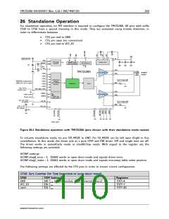
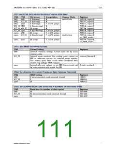
CFG1 AND CFG2: SETS MICROSTEP RESOLUTION FOR STEP INPUT
CFG2, CFG1
GND, GND
GND, VCC_IO
GND, open
VCC_IO, GND
VCC_IO, VCC_IO
VCC_IO, open
open, GND
open, VCC_IO
Microsteps
1 (Fullstep)
2 (Halfstep)
2 (Halfstep)
4 (Quarterstep)
16 µsteps
4 (Quarterstep)
16 µsteps
4 (Quarterstep)
Interpolation
N
N
Y, to 256 µsteps
N
N
Y, to 256 µsteps
Y, to 256 µsteps
Y, to 256 µsteps stealthChop
Chopper Mode
spreadCycle
Registers
MRES=8, intpol=0
MRES=7, intpol=0
MRES=7, intpol=1
MRES=6, intpol=0
MRES=4, intpol=0
MRES=6, intpol=1
MRES=4, intpol=1
MRES=6, intpol=1,
en_PWM_mode=1
MRES=4, intpol=1,
en_PWM_mode=1
open, open
16 µsteps
Y, to 256 µsteps
CFG3: SETS MODE OF CURRENT SETTING
CFG3
Current Setting
Registers
GND
Internal reference voltage. Current scale set by sense
resistors, only.
VCC_IO
open
Internal sense resistors. Use analog input current on internal_Rsense=1
AIN as reference current for internal sense resistor.
This setting gives best results when combined with
stealthChop voltage PWM chopper.
External reference voltage on pin AIN. Current scale set I_scale_analog=1
by sense resistors and scaled by AIN.
CFG4: SETS CHOPPER HYSTERESIS (TUNING OF ZERO CROSSING PRECISION)
CFG4
GND
HEND Setting
5 (recommended, most universal choice)
Registers
HEND=7
VCC_IO
open
9
13
HEND=11
HEND=15
CFG5: SETS CHOPPER BLANK TIME (DURATION OF BLANKING OF SWITCHING SPIKE)
CFG5
GND
VCC_IO
open
Blank time (in number of clock cycles)
16
24 (recommended, most universal choice)
36
Registers
TBL=%00
TBL=%01
TBL=%10
www.trinamic.com

 TRINAMIC [ TRINAMIC MOTION CONTROL GMBH & CO. KG. ]