TMC5130A DATASHEET (Rev. 1.14 / 2017-MAY-15)
110
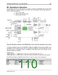
26 Standalone Operation
For standalone operation, no SPI interface is required to configure the TMC5130A. All pins with suffix
CFG0 to CFG6 have a special meaning in this mode. They are evaluated using tristate detection, in
order to differentiate between
CFG pin tied to GND
CFG pin open (no connection)
CFG pin tied to VCC_IO
22n
63V
100n
16V
+VM
Optional use lower
voltage down to 6V
+VM
VS
VSA
5V Voltage
regulator
100n
100n
100µF
charge pump
Full Bridge A
Step&Dir input
with microPlyer
DAC Reference
5VOUT
100n
4.7µ
IREF
2R2
VCC
OA1
OA2
470n
N
TMC5130A
stepper
motor
CFG0
CFG1
CFG2
CFG3
CFG4
CFG5
S
Use low inductivity SMD
type, e.g. 1206, 0.5W
Configuration
interface
with TRISTATE
detection
TRISTATE configuration
(GND, VCC_IO or open)
RSA
BRA
Sequencer
Driver
Opt. driver
enable input
B.Dwersteg, ©
TRINAMIC 2014
DRV_ENN_CFG6
OB1
OB2
DIAG1
DIAG0
Full Bridge B
Index pulse
Driver error
Status out
(open drain)
opt. ext. clock
12-16MHz
CLK_IN
VCC_IO
Use low inductivity SMD
type, e.g. 1206, 0.5W
+VIO
RSB
BRB
3.3V or 5V
I/O voltage
100n
leave open
Figure 26.1 Standalone operation with TMC5130A (pins shown with their standalone mode names)
To activate standalone mode, tie pin SPI_MODE to GND. Pin SD_MODE can be left open (high) in this
constellation. In this mode, the driver acts as a pure STEP and DIR driver. SPI and single wire are off.
The driver works in spreadCycle mode or stealthChop mode. With regard to the register set, the
following settings are activated:
GCONF settings:
GCONF.diag0_error = 1: DIAG0 works in open drain mode and signals driver error.
GCONF.diag1_index = 1: DIAG1 works in open drain mode and signals microstep table index position.
The following settings are affected by the CFG pins in order to ensure correct configuration:
CFG0: SETS CHOPPER OFF TIME (DURATION OF SLOW DECAY PHASE)
CFG0
GND
TOFF Setting
140 TCLK (recommended, most universal choice)
Registers
TOFF=4
VCC_IO
open
236 TCLK
332 TCLK
TOFF=7
TOFF=10
www.trinamic.com

 TRINAMIC [ TRINAMIC MOTION CONTROL GMBH & CO. KG. ]