Features of the Vector Engine (VE)
Qꢀ
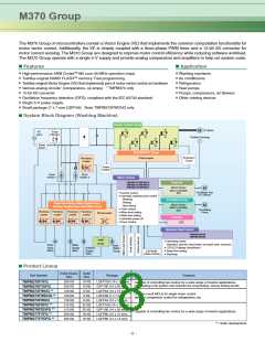
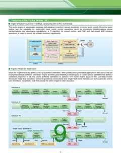
High-efficiency motor control, reducing the CPU workload
The vector engine is a dedicated hardware unit designed to perform various operations for motor vector control. Since the vector
engine has the capability for performing basic vector control operations (such as coordinate transformations, phase
transformations and sine/cosine calculations), a PI algorithm for current control, and PMD and high-speed ADC interface
operations, it helps to reduce the software workload significantly.
Inverter
Motor
CPU: ARM CortexTM-M3
Speed Control
Programmable Motor Driver
(PMD)
Vector Engine (VE)
Current Control
dqAUVW Conversion
Sampling Timing Calculation
Output Interfacing
Output PWM Gen.
Sampling Trigger Gen.
12-Bit ADC
Position
Estimation
Input Interfacing
Sampling Control
UVWAdq Conversion
Current Detection Unit
Software
Hardware
Qꢀ
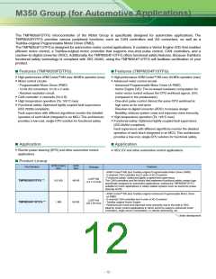
Highly flexible hardware
Since the requirements for speed control and position estimation differ greatly among individual applications and users, they can
be implemented via software. The vector engine provides great flexibility in allowing you to create various schedules that define a
combined sequence of VE and user’s software operations to perform. The vector engine supports two operating modes:
Scheduled mode that executes a series of operations consecutively and Single Task mode that executes individual tasks one by
one. Schedules can select a task that causes the vector engine to start execution.
Schedule #1
Coordinate
Transform
dqA_`
Phase
Transform
2A3
Phase
Transform
3A2
Coordinate
Transform
_`Adq
Current
Control (PI) Calculations
SIN/COS
Trigger
Control
Output
Input
Data Set
Trigger
Interrupt
PMD
ADC
Schedule #4
Coordinate
Transform
dqA_`
Phase
Transform
2A3
Phase
Transform
3A2
Coordinate
Transform
_`Adq
SIN/COS
Calculations
Trigger
Control
Output
Input
Data Set
Trigger
Interrupt
PMD
ADC
Schedule #9
Trigger
Control
Output
Input
Data Set
Trigger
Interrupt
PMD
ADC
Single Task & Schedule #1
Single Task Execution
Schedule #1
Output
Coordinate
Transform
dqA_`
Phase
Transform
2A3
Phase
Transform
3A2
Coordinate
Transform
_`Adq
Trigger
Control
Input
Schedule #1
Data
Set
Start
Interrupt
Start
Interrupt
Trigger
Start
Interrupt
Task Selection
Task Selection
PWM Freq. Adjustment
PMD
ADC
–
–
9

 TOSHIBA [ TOSHIBA ]