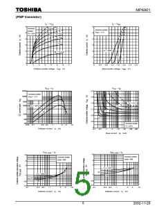
MP6901
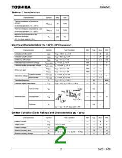
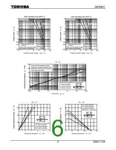
Safe Operating Area (NPN Tr)
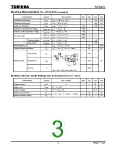
Safe Operating Area (PNP Tr)
10
−10
I
max (pulsed)*
I
max (pulsed)*
C
C
5
3
−5
−3
10 ms
100 µs
10 ms
100 µs
1 ms
1 ms
1
−1
0.5
0.3
−0.5
−0.3
0.1
−0.1
0.05
0.03
−0.05
−0.03
*: Single nonrepetitive pulse
Tc = 25°C
Curves must be derated linearly
with increase in temperature.
*: Single nonrepetitive pulse
Tc = 25°C
Curves must be derated linearly
with increase in temperature.
V
max
V
max
CEO
CEO
0.01
−0.01
0.5
1
3
10
30
100
(V)
300
−0.5 −1
−3
−10
−30
−100
−300
Collector-emitter voltage
V
Collector-emitter voltage
V
(V)
CE
CE
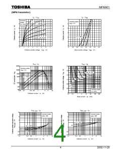
r
th
– t
w
300
Curves should be applied in thermal
limited area. (single nonrepetitive pulse)
Below figure show thermal resistance per
1 unit versus pulse width.
(3)
100
(2)
(1)
30
10
3
1
-No heat sink and attached on a circuit board-
(1) 1 device operation
(2) 3 devices operation
NPN
PNP
(3) 6 devices operation
Circuit board
0.3
0.001
0.01
0.1
1
10
100
1000
Pulse width
t
(s)
w
∆T – P
P – Ta
T
j
T
(1) 1 device operation
(2) 3 devices operation
(3) 8 devices operation
(1)
(2) (3)
120
80
40
0
6
4
2
0
Attached on a circuit board
(3)
(2)
Circuit board
(1)
Circuit board
Attached on a circuit board
(1) 1 device operation
(2) 3 devices operation
(3) 6 devices operation
0
2
4
6
8
10
0
40
80
120
160
200
Total power dissipation
P
(W)
Ambient temperature Ta (°C)
T
6
2002-11-20

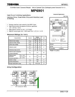
 TOSHIBA [ TOSHIBA ]