ADVANCED INFORMATION
TK654xx
THEORY OF OPERATION (CONT.)
cycle will be dependent upon the duration of the preceding
"on" cycle and the sensed input and the output voltages.
As the battery voltage drops, the voltage on the VLBI pin will
dropproportionately. WhenthevoltageontheLBIinputpin
passes through approximately 1.22 V, the output of the
first comparator (LBO) will transition from a high to a low
state and the synchronous rectifier N-channel MOSFET
willstopbeingswitched.Thereisabout50mVofhysteresis
betweentheLBOtrippointanditsresetpoint. Shortlyafter
the LBO output has been asserted, as the input voltage
continues to drop, the magnitude of the current out of the
VLBI pin will begin to flow and proportionately increase as
the input voltage decreases. An op-amp feedback loop
internal to the Battery Monitor of the TK654xx will attempt
to maintain the voltage on the VLBI pin at a constant value
of approximately 1.22 V (thus, the plateau). As the battery
voltage continues to drop, there comes a point where the
feedback current stops increasing at about 720 nA. At this
point, the voltage on the LBI pin will resume a proportional
drop with the input voltage and the TK654xx converter will
turn off.
Theapproximatedurationofthe"off"cyclecanbepredicted
as follows:
T
= T
X (V - V
) / V
OUT OUT
OFF
ON
IN
During the majority of the "off" cycle, a power switch is
turned on. The turn-on point of the switch is synchronized
withtheinitiationofthe"off"cycle. Theturn-offpointisnear
the end of the "off" cycle. The addition of this switch
reduces the voltage drop across the external rectifying
deviceandprovidessignificantimprovementsinconverter
efficiency.
BATTERY MONITOR SECTION
Inatypicalvoltagemonitor,whichusesanexternalresistive
divider for setting the voltage monitor threshold, the input
bias current to the monitor pin is essentially zero. In this
type of scenario, the voltage on the monitor input would be
a resistively divided version of the battery voltage. The
BatteryMonitoroftheTK654xxintroducesasmallfeedback
current (-ILBI) which introduces a “plateau” into the transfer
characteristicsbetweenthebatteryvoltageandthevoltage
monitoring pin. The width of this plateau is dependent
upon the current range of the feedback current (-ILBI) and
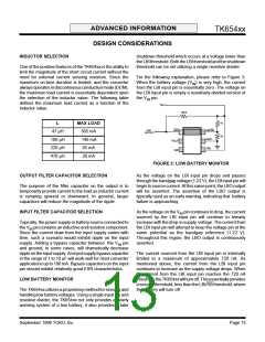
the values of the external resistor network. Figure 2
illustrates the typical relationship between the battery
voltage (VIN), the feedback current (-ILBI) and the voltage
on the monitoring pin (VLBI).
For details on how to properly select the resistor divider,
refer to the “Design Considerations” section.
V
LBO
V
IN
V
OFF
1.22 V
V
LBI
720 nA
0 nA
-I
LBI
In selecting a resistor divider network, there are typically
two degrees of freedom when selecting values. The first
criteria in selecting the divider is the ratio of the two
resistors. Selecting the ratio defines the upper threshold of
the voltage monitor. The second degree of freedom when
selecting the resistor divider is the absolute resistance
values. This second degree of freedom can be utilized to
set a secondary monitoring threshold (VOFF) lesser than
the first.
LBO
OFF
FIGURE 2: BATTERY MONITOR OPERATION
GRAPHS
Typically, when the battery voltage is relatively high, the
voltage on the LBI input pin will be a resistively divided
version of the battery voltage.
September 1999 TOKO, Inc.
Page 11

 TOKO [ TOKO, INC ]