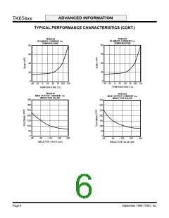
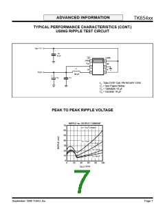
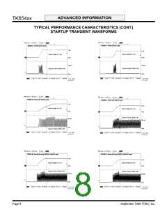
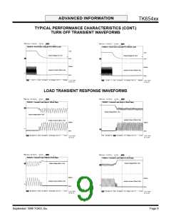
ADVANCED INFORMATION
TK654xx
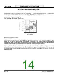
THEORY OF OPERATION
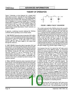
SW1
L
Figure 1 illustrates a circuit diagram for a simple buck
V
OUT
(step-down) converter. Typically, the input voltage (V ) is
IN
+
greater than the output voltage (V
). By modulating the
OUT
D
C
V
IN
switching action of switch SW1, the output voltage (V
)
OUT
can be regulated to a constant voltage that is relatively
independent of variations in the input supply (V ) or the
IN
current load on the V
node. The TK654xx contains all
OUT
FIGURE 1: SIMPLE "BUCK" CONVERTER
the control circuitry, logic, and power switch (SW1) for
implementing a simple step-down or "buck" converter, as
shown in Figure 1.
The control scheme for the TK654xx forces the converter
tostepthroughthe"on,""off,"and"null"statesinsequence.
Assume that the controller is initially in the "null" state and
In general, a switching converter utilizing the TK654xx
controller will be operating in one of three states:
V
is greater than the regulation threshold. As soon as
OUT
theoutputvoltagedropsbelowthisthreshold,thecontroller
willswitchfrom"null"statetothe"on"state. Duringthe"on"
state, current through inductor (L) will be increasing.
Current will flow from the input supply to the output
capacitor through the inductive element. In this state,
energy is transferred directly from the input supply to the
output through the inductor. The maximum duration of the
"on"stateisinverselyproportionaltothedifferencebetween
1. "ON" STATE: During this state of operation SW1 will be
turnedon. Currentthroughtheinductiveelement(L)willbe
increasing at a rate proportional to the voltage difference
between V and V
. In this state, there is a direct
IN
OUT
current path from the input supply to the output load
through the inductor L.
2. "OFF" STATE: During this state of operation SW1 will
be turned off. Current through the inductive element will be
greater than zero and flowing either through the external
schottkyrectifier(D)orthesynchronousrectifierinternalto
the TK654xx. During the "off" state, current through the
inductive element (L) will be decreasing at a rate
the input voltage (V ) and the output voltage (V
).
IN
OUT
The transition from the "on" state to the "off" state can be
initiated by one of two different means. As mentioned
above, the maximum duration of the "on" state is inversely
proportional to the difference between the input voltage
approximately proportional to V
. In this state, the
(V ) and the output voltage (V
). If the duration of the
OUT
IN
OUT
current drawn from the input supply is essentially zero.
Current to the load is provided by stored energy in the
inductive element.
"on" cycle exceeds this maximum, the controller
immediately switches to the "off" state independent of
other factors. Understanding that when the converter is in
a dropout condition (V ≈ V
), the maximum “on” time
IN
OUT
3. "NULL" STATE: During this state of operation SW1 will
be turned off. Current through the inductive element will be
approximately zero. The internal synchronous rectifier will
be turned off. All current demands of the load will be
provided by the output filter capacitor (C). In this state, the
current drawn from the input supply is essentially zero.
Since the inductive current is zero, no additional energy is
available from the inductor. If the current demands of the
load are very light, the current will be provided by the
stored charge in the output filter capacitor. If the voltage of
thefiltercapacitordropsbelowtheregulationthreshold, an
"on" state will be initiated and additional energy will be
transferred from the input supply to the output.
is infinite and the “on” state is constantly applied. By
limiting the duration of the "on" cycle, the peak inductor
current is also being limited. The second method for
initiatingthe"off"cycleistriggeredwhenthedurationofthe
"on" cycle exceeds a minimum on-time duration and the
output voltage (V
) exceeds the regulation threshold.
OUT
Therefore, the actual duration of the "on" cycle will vary
between a minimum on-time (T ) and a maximum
ON(MIN)
on-time (T
) depending upon the load current. At
ON(MAX)
very light loads the on-time duration will be at a minimum;
at very heavy loads the on-time will be at a maximum. This
ability to vary the duration of the on cycle is a proprietary
control scheme which can produce a ten-fold reduction in
ripple when compared to competing devices.
The transition from the "off" state to the "null" state occurs
after sufficient time has been allowed for the inductor
current to return to zero. The actual duration of the "off"
Page 10
September 1999 TOKO, Inc.

 TOKO [ TOKO, INC ]