ꢠ ꢆꢁꢡꢡ ꢢ
www.ti.com
SBOS344 − SEPTEMBER 2005
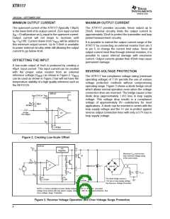
protection diode is used, a series diode or diode bridge
should be used for protection against reversed
connections.
OVER-VOLTAGE SURGE PROTECTION
Remote connections to current transmitters can
sometimes be subjected to voltage surges. It is prudent
to limit the maximum surge voltage applied to the
XTR117 to as low as practical. Various zener diode and
surge clamping diodes are specially designed for this
purpose. Select a clamp diode with as low a voltage
rating as possible for best protection. Absolute
maximum power-supply rating on the XTR117 is
specified at +50V. Keep overvoltages and transients
below +50V to ensure reliable operation when the
supply returns to normal (7.5V to 40V).
RADIO FREQUENCY INTERFERENCE
The long wire lengths of current loops invite radio
frequency (RF) interference. RF interference can be
rectified by the input circuitry of the XTR117 or
preceding circuitry. This effect generally appears as an
unstable output current that varies with the position of
loop supply or input wiring. Interference may also enter
at the input terminals. For integrated transmitter
assemblies with short connections to the sensor, the
interference more likely comes from the current loop
connections.
Most surge protection zener diodes have a diode
characteristic in the forward direction that will conduct
excessive current, possibly damaging receiving-side
circuitry if the loop connections are reversed. If a surge
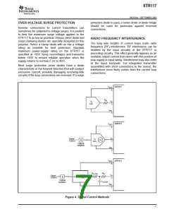
XTR117
VREG
8
RIN
IIN
2
VO
D/A
IRET
3
XTR117
VREG
8
IIN
2
IO
D/A
Digital
Control
Optical
Isolation
IRET
3
VREG XTR117
8
RFILTER
RIN
IIN
2
PWM
Out
Digital
Control
µ
C
Optical
Isolation
CFILTER
IRET
3
Figure 4. Digital Control Methods
7

 TI [ TEXAS INSTRUMENTS ]