UCD90320
ZHCSFI3B –AUGUST 2016–REVISED MAY 2019
www.ti.com.cn
In the scenario where several faults happen immediately before the brownout event, the device requires a
capacitance of 500 µs in order to write the first fault event into the EEPROM. The write function requires an
additional 4 ms to write the Black Box fault log into the EEPROM. Therefore, in order to preserve at least the first
fault log, user must provide enough local capacitance to maintain the V33D rail above VSHDN for 500 µs (or
4.5ms with the Black Box fault log). Longer holdup time allows more fault events to be written into the EEPROM
during brownout.
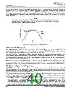
NOTE
The hold-up time is affected by V33D rail capacitance, the UCD90320 supply current and
external circuits that source current from the rail (such as LEDs, load current on I/O pins,
and other devices powered by the same rail).
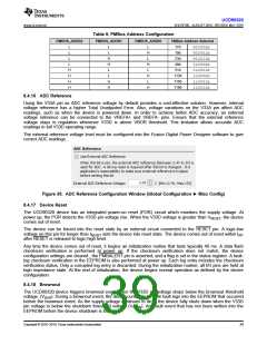
V
V33D(min)
V
V
BOR
VRESET
SHDN
Time
Figure 36. Reset and Brownout Thresholds
8.4.19 Internal Fault Management
The UCD90320 device verifies the firmware by using a checksum algorithm at each power up. If the checksum
does not match, the device resets. If the device continues to reset, the SYNC_CLK pin outputs repeated pulses
with an approximate 250-ms pulse width that can be observed externally.
The device performs a configuration checksum verification at power up. If the checksum does not match, the
device discards all the configuration data. The PMBALERT pin is asserted and a flag is set in the status register.
A fault-log checksum verification in EEPROM is also performed at power up. Each log entry has a checksum.
The device discards corrupted log entries.
If the internal firmware watchdog timer times out, the device resets. If the firmware program is corrupted, the
device returns to a known state. This return function is normal, so all of the I/O pins are held in high-impedance
while the device is in reset. The process confirms each parameter to ensure it falls within the acceptable range.
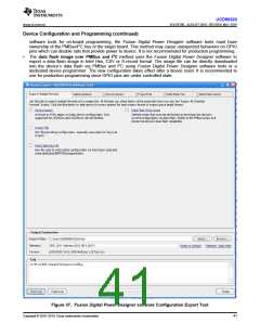
8.5 Device Configuration and Programming
UCD90320 devices include factory-installed sequencing and monitoring firmware. All I/O pins are pre-configured
ad high-impedance, with no sequencing or fault-response operation. Use the Fusion Digital Power Designer
software to configure the device on-line or off-line. Generate a configuration file after configuring the device and
import that configuration into other UCD90320 devices.
The Configuration Programming of UCD Devices section of the Documentation & Help Center offers
configuration and programming details and can be accessed under the Fusion Digital Power Designer software
Help menu. In general, UCD90320 supports two programming methods:
•
The PMBus command over PMBus and I2C method uses a PMBus host to program the device. The PMBus
host can be either a host microcontroller or Fusion Digital Power Designer software tools. Each PMBus
command sends a corresponding parameter(s) into the device. The new parameters are stored in its
associated memory (RAM) location. After all the parameters are sent into the device, the PMBus host issues
a special command, STORE_DEFAULT_ALL, which writes the RAM data into nonvolatile memory (data
flash). Fusion GUI normally uses this method to configure a device. If using Fusion Digital Power Designer
40
Copyright © 2016–2019, Texas Instruments Incorporated

 TI [ TEXAS INSTRUMENTS ]