UCC28740
www.ti.com
SLUSBF3A –JULY 2013–REVISED JULY 2013
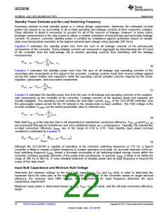
The UCC28740 maintains tight constant-current regulation over varying input line by using the line-compensation
feature. The line-compensation resistor (RLC) value is determined by current flowing in RS1 and the total internal
gate-drive and external MOSFET turnoff delay. Assume an internal delay of 50 ns in the UCC28740.
K
´R ´R ´ t ´N
LC
S1
CS
D
PA
R
=
LC
L
P
(25)
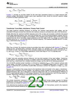
Output Capacitance
The output capacitance value is often determined by the transient-response requirement from the no-load
condition. For example, in typical low-power USB-charger applications, there is a requirement to maintain a
minimum transient VO of 4.1 V with a load-step ITRAN from 0 mA to 500 mA. Yet new higher-performance
applications require smaller transient voltage droop VOΔ with ITRAN of much greater amplitude (such as from no-
load to full-load), which drives the need for high-speed opto-coupled voltage feedback.
where
•
tRESP is the time delay from the moment ITRAN is applied to the moment when IFB falls below 1 µA
(26)
Additional considerations for the selection of appropriate output capacitors include ripple-current, ESR, and ESL
ratings necessary to meet reliability and ripple-voltage requirements. Detailed design criteria for these
considerations are beyond the scope of this datasheet.
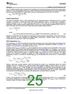
VDD Capacitance, CVDD
The capacitance on VDD must supply the primary-side operating current used during startup and between low-
frequency switching pulses. The largest result of three independent calculations denoted in Equation 27,
Equation 28, and Equation 29 determines the value of CVDD
.
At startup, when VVDD(on) is reached, CVDD alone supplies the device operating current and MOSFET gate current
until the output of the converter reaches the target minimum-operating voltage in CC regulation, VOCC. Now the
auxiliary winding sustains VDD for the UCC28740 above UVLO. The total output current available to the load and
to charge the output capacitors is the CC-regulation target, IOCC. Equation 27 assumes that all of the output
current of the converter is available to charge the output capacitance until VOCC is achieved. For typical
applications, Equation 27 includes an estimated qGfSW(max) of average gate-drive current and a 1-V margin added
to VVDD
.
(27)
During a worst-case un-load transient event from full-load to no-load, COUT overcharges above the normal
regulation level for a duration of tOV, until the output shunt-regulator loading is able to drain VOUT back to
regulation. During tOV, the voltage feedback loop and optocoupler are saturated, driving maximum IFB and
temporarily switching at fSW(min). The auxiliary bias current expended during this situation exceeds that normally
required during the steady-state no-load condition. Equation 28 calculates the value of CVDD (with a safety factor
of 2) required to ride through the tOV duration until steady-state no-load operation is achieved.
(28)
Finally, in the steady-state no-load operating condition, total no-load auxiliary-bias current, IAUXNL is provided by
the converter switching at a no-load frequency, fSWNL, which is generally higher than fSW(min). CVDD is calculated to
maintain a target VDD ripple voltage lower than ΔVVDD, using Equation 29.
Copyright © 2013, Texas Instruments Incorporated
Submit Documentation Feedback
25
Product Folder Links: UCC28740

 TI [ TEXAS INSTRUMENTS ]