UC1854
UC2854
UC3854
o
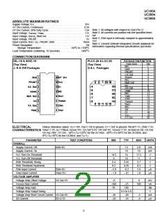
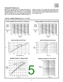
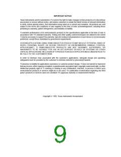
TYPICAL CHARACTERISTICS at TA = TJ = 25 C (cont.)
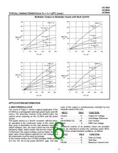
Multiplier Output vs Multiplier Inputs with Mult Out=0V
250
600
500
400
V
RMS=1.5V
VRMS=3V
VA Out=5V
200
150
VA Out=3.5V
VA Out=3V
300
Mult Out
VA Out=2.5V
VA Out=1.25V
Mult Out
µA
100
µA
200
VA Out=2V
50
0
100
0
VA Out=1.25V
0
100
200
300
400
500
0
100
200
300
AC, µA
400
500
I
AC, µA
I
140
160
140
120
100
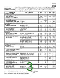
V
RMS=5V
V
RMS=4V
VA Out=5V
120
100
VA Out=5V
VA Out=4V
VA Out=3V
Mult Out
80
Mult Out,
VA Out=3V
80
µA
µA
60
60
40
VA Out=2V
40
VA Out=1.5V
VA Out=1.25V
20
0
20
0
0
0
100
200
IAC,
300
400
500
100
200
300
µA
400
500
µ
A
IAC,
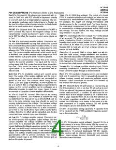
APPLICATIONS INFORMATION
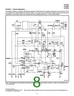
A 250W PREREGULATOR
The circuit of Figure 1 shows a typical application of the
UC3854 as a preregulator with high power factor and effi-
ciency. The assembly consists of two distinct parts, the
control circuit centering on the UC3854 and the power
section.
The power section is a "boost" converter, with the induc-
tor operating in the continuous mode. In this mode, the
duty cycle is dependent on the ratio between input and
output voltages; also, the input current has low switching
frequency ripple, which means that the line noise is low.
Furthermore, the output voltage must be higher than the
peak value of the highest expected AC line voltage, and
all components must be rated accordingly.
cycle of this output is simultaneously controlled by four
separate inputs to the chip:
INPUT
PIN #
FUNCTION
VSENSE........................11 .......... Output DC Voltage
IAC.................................6 .......... LineVoltage Waveform
ISENSE/Mult Out .........4/5 .......... Line Current
VRMS.............................8 .......... RMS Line Voltage
Additional controls of an auxiliary nature are provided.
They are intended to protect the switching power MOS-
FETS from certain transient conditions, as follows:
INPUT
PIN #
FUNCTION
ENA ............................10 .......... Start-Up Delay
SS...............................13 .......... Soft Start
PKLIM...........................2 .......... Maximum Current Limit
In the control section, the UC3854 provides PWM pulses
(GT Drv, Pin 16) to the power MOSFET gate. The duty
6

 TI [ TEXAS INSTRUMENTS ]