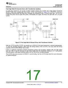
UC2625-EP
www.ti.com .................................................................................................................................................................................................. SLUS802–MARCH 2008
Power Stage Design
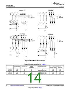
The UC2625 is useful in a wide variety of applications, including high-power in robotics and machinery. The
power output stages used in such equipment can take a number of forms, according to the intended performance
and purpose of the system. Figure 8 show four different power stages with the advantages and disadvantages of
each.
For high-frequency chopping, fast recovery circulating diodes are essential. Six are required to clamp the
windings. These diodes should have a continuous current rating at least equal to the operating motor current,
since diode conduction duty-cycle can be high. For low-voltage systems, Schottky diodes are preferred. In higher
voltage systems, diodes such as Microsemi UHVP high voltage platinum rectifiers are recommended.
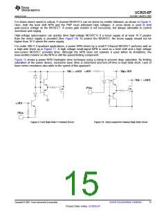
In a pulse-by-pulse current control arrangement, current sensing is done by resistor RS, through which the
transistor's currents are passed (Fig. A, B, and C). In these cases, RD is not needed. The low-side circulating
diodes go to ground and the current sense terminals of the UC2625 (ISENSE1 and ISENSE2) are connected to RS
through a differential RC filter. The input bias current of the current sense amplifier causes a common mode
offset voltage to appear at both inputs, so for best accuracy, keep the filter resistors below 2 kΩ and matched.
The current that flows through RS is discontinuous because of chopping. It flows during the on time of the power
stage and is zero during the off time. Consequently, the voltage across RS consists of a series of pulses,
occurring at the PWM frequency, with a peak value indicative of the peak motor current.
To sense average motor current instead of peak current, add another current sense resistor (RD in Fig. D) to
measure current in the low-side circulating diodes, and operate in four quadrant mode (pin 22 high). The
negative voltage across RD is corrected by the absolute value current sense amplifier. Within the limitations
imposed by Table 1, the circuit of Fig. B can also sense average current.
Copyright © 2008, Texas Instruments Incorporated
Submit Documentation Feedback
13
Product Folder Link(s) :UC2625-EP

 TI [ TEXAS INSTRUMENTS ]