UC1517
UC3517
used in conjunction with discrete power transistors or
power driver ICs, like the L298. These can be connected
as current gain devices that turn on when the phase out-
puts turn on.
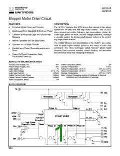
INH: When the inhibit input is high, the phase and θ out-
puts are inhibited (high impedance). STEP pulses re-
ceived while inhibited will continue to update logic in the
IC, but the states will not be reflected at the outputs until
inhibit is pulled low. In stepper motor systems, this can be
used to save power or to allow the rotor to move freely for
manual repositioning.
Bipolar Motor Drive: Bipolar motors can be controlled by
the UC3517 with the addition of bipolar integrated drivers
such as the UC3717A (Figure 8) and the L298, or discrete
devices. Care should be taken with discrete devices to
avoid potential cross-conduction problems.
OPERATING MODES
The UC3517 is a system component capable of many dif-
ferent operating modes, including:
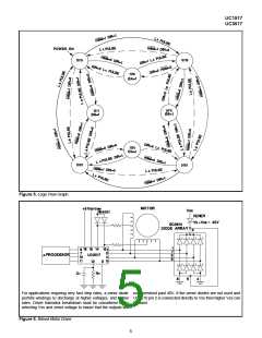
LOGIC FLOW GRAPH
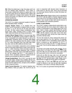
The UC3517 contains a bidirectional counter which is de-
coded to generate the correct phase and Ø outputs. This
counter is incremented on every falling edge of the STEP
input. Figure 5 shows a graph representing the counter
sequence, inputs that determine the next state (DIR and
HSM), and the outputs at each state. Each circle repre-
sents a unique logic state, and the four inside circles rep-
resent the half-step states.
Unipolar Stepper Driver: In its simplest form, the
UC3517 can be connected to a stepper motor as a unipo-
lar driver. LA, LB, RC and Vss are not used, and may be
left open. All other system design considerations men-
tioned above apply, including choice of motor supply
VMM, undershoot diodes and timing considerations.
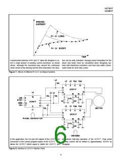
Unipolar Bilevel Stepper Driver: If increased step rates
are desired, the application circuit of Figure 6 makes use
of the monostables and emitter followers as well as the
configuration mentioned above to provide high-voltage
pulses to the motor windings when the phase is turned
on. For a given dissipation level, this mode offers faster
step rates, and very little additional electrical noise.
The four bits inside the circles represent the phase out-
puts in each state (PA1, PA2, PB1, and PB2). For example,
the circle labeled 1010 is immediately entered when the
device is powered up, and represents PA1 off ("1" or
high), PA2 on ("0" or low), PB1 off ("1" or high) and PB2 on
("0" or low). The ØA and ØB outputs are both low (uniden-
tified).
The choice of monostable components can be estimated
based on the timing relationship of motor current and volt-
age: V = Ldl/dt. Assuming a fixed secondary supply volt-
age (VSS), a fixed winding inductance (LM), a desired
winding peak current (IW), and no back EMF from the mo-
tor, we can estimate that RTCT = 1.449 IWLM/VSS. In
practice, these calculations should be confirmed and ad-
justed to accommodate for effects not modeled.
The arrows in the graph show the state changes. For ex-
ample, if the IC is in state 0110, DIR is high, HSM is high,
and STEP falls, the next state will be 0101, and a pulse
will be generated on the LB line by the monostable.
Inhibit will not effect the logic state, but it will cause all
phase outputs and both Ø outputs to go high (off). A fall-
ing edge on STEP will still cause a state change, but in-
hibit will have to toggle low for the state to be apparent.
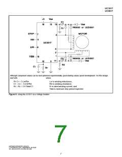
Voltage-Doubled Mode: The UC3517 can also be used
to generate higher voltages than available with the sys-
tem power supplies using capacitors and diodes. Figure 9
shows how this might be done, and gives some estimates
for the component values.
A falling edge on STEP with HSM high will cause the
counter to advance to the next full step state regardless
of whether or not it was in a full step state previously.
Higher Current Operation: For systems requiring more
than 350mA of drive per phase, the UC3717A can be
No LA or LB pulses are generated entering half-states.
4

 TI [ TEXAS INSTRUMENTS ]