TUSB1310A
www.ti.com
SLLSE32D–NOVEMBER 2010–REVISED MAY 2011
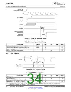
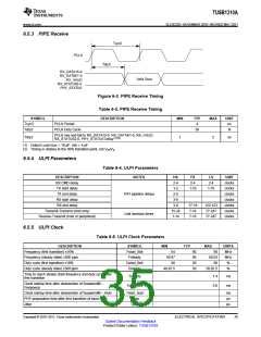
6.5.3 PIPE Receive
Tcyc3
PCLK
Tdly3
RX_DATA15-0
RX_DATAK1-0
RX_VALID
Valid Data
RX_STATUS2-0
PHY_STATUS
Figure 6-3. PIPE Receive Timing
Table 6-3. PIPE Receive Timing
SYMBOL
Tcyc3
DESCRIPTION
MIN
TYP
4
MAX
UNIT
ns
PCLK Period
Tdty3
PCLK Duty Cycle
50
%
PCLK rise and fall to RX_DATA15-0, RX_DATAK1-0, RX_VALID,
RX_STATUS2-0, PHY_STATUS Delay(1)(2)
Tdly3
1
2
ns
(1) Output Load max = 10 pF, min = 5 pF
(2) Timing is relative to the 50% transition point, not VIH/VIL.
6.5.4 ULPI Parameters
Table 6-4. ULPI Parameters
DESCRIPTION
RX CMD delay
NOTES
HS
FS
LS
2-4
UNIT
clocks
clocks
clocks
clocks
clocks
clocks
clocks
2-4
1-2
2-4
TX start delay
1-10
1-10
TX end delay
PHY pipeline delays
2-5
RX start delay
3-8
RX end delay
3-8
17-18
7-18
7-18
122-123
77-247
77-247
Transmit-Transmit (host only)
Receive-Transmit (host or peripheral)
15-24
1-14
Link decision times
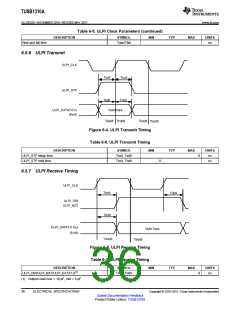
6.5.5 ULPI Clock
Table 6-5. ULPI Clock Parameters
DESCRIPTION
Frequency (first transition) ±10%
SYMBOL
Fstart_8bit
Fsteady
MIN
TYP
MAX
66
UNITS
MHz
MHz
%
54
60
60
50
50
Frequency (steady state) ±500 ppm
Duty cycle (first transition) ±10%
Duty cycle (steady state) ±500 ppm
59.97
60.03
60
Dstart_8bit
Dsteady
40
49.97 5
50.02 5
%
Time to reach steady state frequency and duty cycle after
first transition
Tsteady
1.4
5.6
ms
ms
Clock startup time after deassertion of SuspemdM –
Peripheral
Tstart_dev
Clock startup time after deassertion of SuspemdM – Hold
PHY preparation time after first transition of input clock
Jitter
Tstart_host
Tprep
ms
µs
ps
Tjitter
Copyright © 2010–2011, Texas Instruments Incorporated
ELECTRICAL SPECIFICATIONS
35
Submit Documentation Feedback
Product Folder Link(s): TUSB1310A

 TI [ TEXAS INSTRUMENTS ]