TPS61196
SLVSBG1C –OCTOBER 2012–REVISED FEBRUARY 2013
www.ti.com
Switch MOSFET and Gate Driver Resistor
The TPS61196 demands a power N-MOSFET (see Q1 in SIMPLIFIED SCHEMATIC CIRCUIT) as a switch. The
voltage and current rating of the MOSFET must be higher than the application output voltage and the inductor
peak current. The applications benefit from the addition of a resistor (See R19 in SIMPLIFIED SCHEMATIC
CIRCUIT) connected between the GDRV pin and the gate of the switch MOSFET. With this resistor, the gate
driving current is limited and the EMI performance is improved. A 3-Ω resistor value is recommended. The
TPS61196 exhibits lower efficiency when the resistor value is above 3Ω due to the more switching loss of the
external MOSFET.
Current Sense and Current Sense Filtering
R7 determines the correct over current limit protection. To choose the right value of R7, start with the total
system power needed POUT, and calculate the input current IIN by Equation 7. Efficiency can be estimated
between 90% to 95%. The second step is to calculate the inductor peak current based on the inductor value L
using Equation 8 and Equation 9. The maximum R7 can now be calculated as R7(max) = VISNS / IL(P). It is
recommended to add 20% or more margins to account for component variations. A small filter placed on the
ISNS pin improves performance of the converter (See R6 and C5 in SIMPLIFIED SCHEMATIC CIRCUIT). The
time constant of this filter should be approximately 100ns. The range of R6 should be from about 100Ω to 1kΩ
for best results. The C5 should be located as close as possible to the ISNS pin to provide noise immunity.
Output Capacitor
The output capacitor is mainly selected to meet the requirements for output ripple and loop stability of the whole
system. This ripple voltage is related to the capacitance of the capacitor and its equivalent series resistance
(ESR). Assuming a capacitor with zero ESR, the minimum capacitance needed for a given ripple can be
calculated by:
IOUT ´ DMAX
VRIPPLE(C)
=
fSW ´ COUT
(10)
Where VRIPPLE is the peak to peak output voltage ripple and DMAX is the duty cycle of the boost converter.
DMAX is approximately equal to (VOUT(MAX) – VIN(MIN) / VOUT(MAX)) in applications. Care must be taken when
evaluating a capacitor’s derating under DC bias. The DC bias can also significantly reduce capacitance. Ceramic
capacitors can loss as much as 50% of its capacitance at its rated voltage. Therefore, leave the margin on the
voltage rating to ensure adequate capacitance.
The ESR impact on the output ripple must be considered as well if tantalum or aluminum electrolytic capacitors
are used. Assuming there is enough capacitance such that the ripple due to the capacitance can be ignored, the
ESR needed to limit the VRIPPLE is:
VRIPPLE(ESR) = IL(P) ´ ESR
(11)
Ripple current flowing through a capacitor’s ESR causes power dissipation in the capacitor. This power
dissipation causes a temperature increase internally to the capacitor. Excessive temperature can seriously
shorten the expected life of a capacitor. Capacitors have ripple current ratings that are dependent on ambient
temperature and should not be exceeded. Therefore, high ripple current type electrolytic capacitor with small
ESR is used in typical application as shown in SIMPLIFIED SCHEMATIC CIRCUIT.
In the typical application, the output requires a capacitor in the range of 22µF to 220µF. The output capacitor
affects the small signal control loop stability of the boost converter. If the output capacitor is below the range, the
boost regulator may potentially become unstable.
Loop Consideration
The COMP pin on the TPS61196 is used for external compensation, allowing the loop response to be optimized
for each application. The COMP pin is the output of the internal trans-conductance amplifier. The external
resistor R8, along with ceramic capacitors C6 and C8 (see in SIMPLIFIED SCHEMATIC CIRCUIT), are
connected to the COMP pin to provide poles and zero. The poles and zero, along with the inherent pole and zero
in a peak current mode control boost converter, determine the closed loop frequency response. This is important
to converter stability and transient response.
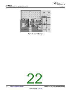
The first step is to calculate the pole and the right half plane zero of the peak current mode boost converter by
Equation 12 and Equation 13.
20
Submit Documentation Feedback
Copyright © 2012–2013, Texas Instruments Incorporated
Product Folder Links :TPS61196

 TI [ TEXAS INSTRUMENTS ]