TPS61196
www.ti.com
SLVSBG1C –OCTOBER 2012–REVISED FEBRUARY 2013
When the IC junction temperature is over 150°C, the thermal protection circuit is triggered and shuts down
the device immediately. The device automatically restarts when the junction temperature falls back to less
than 135°C, with approximate 15°C hysteresis.
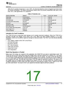
Table 3. Protection List
PROTECTION ITEM
Diode Open
RESULT
FAULT
LATCH OFF / RETRY
Latch off
Can not start up
Output voltage low
LED string off
IFB OVP
Y
Y
Y
Y
Y
Y
Y
Y
Y
Y
Diode Short
Latch off
LED String Open
LED string latch off
Latch off
LED String Short during startup
LED Short
LED string off
Boost off
LED string latch off
Latch off
IFB Short to GND
ISET Short to GND
All LED Strings Open during startup
Input Voltage UVLO
Thermal Shutdown
All LED strings off
VOUT OVP
Boost off
Retry
Latch off
Retry
Shutdown
Retry
Indication for Fault Conditions
The TPS61196 has an open-drain fault indicator pin to indicate abnormal conditions. When the TPS61196 is
operating normally, the voltage at the FAULT pin is low. When any fault condition happens, it is in high
impedance, which can be pulled to high level through an external resistor. The FAULT pin can indicate following
conditions:
•
•
•
•
•
•
•
Over voltage condition at the OVP or the IFB pin
LED short and open
IFB short to ground
ISET short to ground
Diode open and short
Output short circuit
Over temperature
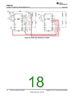
Multi-Chip Operation in Parallel
When more LED strings are required in the application, the TPS61196 can work in master/slave mode. The
TPS61196 can be set as slave device when the voltage at the FSW pin is below 0.5V or above 3.5V. The master
TPS61196 has booster controller and outputs the power rail for all LED strings. The slave TPS61196 only works
as a LED driver and feedbacks the required headroom voltage to the master by connecting the slave's COMP pin
to the master's REF pin. The ISNS pin of the slave TPS61196 must be connected to ground. The slave's OVP
pin voltage must be 3% higher than the voltage at the master's OVP pin. The slave device can combine all fault
conditions happening on both master and slave devices by connecting the master's FAULT output to the FSW
pin of the slave device. The slave’s FAULT pin outputs the indication signal for all fault conditions.
Copyright © 2012–2013, Texas Instruments Incorporated
Submit Documentation Feedback
17
Product Folder Links :TPS61196

 TI [ TEXAS INSTRUMENTS ]