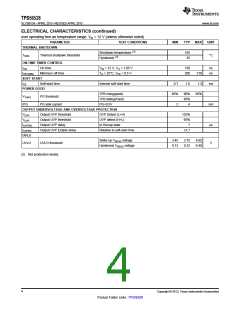
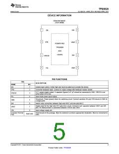
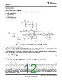
TPS56528
SLVSBV3A –APRIL 2013–REVISED APRIL 2013
www.ti.com
Power Good
The power-good function is activated after soft start has finished. The power good function becomes active after
1.7 times soft-start time. When the output voltage becomes within -10% of the target value, internal comparators
detect power good state and the power good signal becomes high. The power good output, PG is an open drain
output. If the feedback voltage goes under 15% of the target value, the power good signal becomes low.
Output Discharge Control
TPS56528 discharges the output via SW pin when EN is low, or the controller is turned off by the protection
functions(UVP, UVLO and thermal shutdown). The internal regular low-side MOSFET is not turned on during the
output discharge operation to avoid the possibility of causing negative voltage at the output.
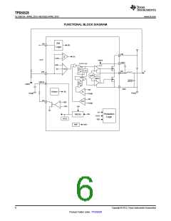
Current Protection
The output overcurrent protection (OCP) is implemented using a cycle-by-cycle valley detect control circuit. The
switch current is monitored by measuring the low-side FET switch voltage between the SW pin and GND. This
voltage is proportional to the switch current. To improve accuracy, the voltage sensing is temperature
compensated.
During the on time of the high-side FET switch, the switch current increases at a linear rate determined by VIN,
VOUT, the on-time and the output inductor value. During the on time of the low-side FET switch, this current
decreases linearly. The average value of the switch current is the load current Iout. The TPS56528 constantly
monitors the low-side FET switch voltage, which is proportional to the switch current, during the low-side on-time.
If the measured voltage is above the voltage proportional to the current limit, an internal counter is incremented
per each SW cycle and the converter maintains the low-side switch on until the measured voltage is below the
voltage corresponding to the current limit at which time the switching cycle is terminated and a new switching
cycle begins. In subsequent switching cycles, the on-time is set to a fixed value and the current is monitored in
the same manner. If the over current condition exists for 7 consecutive switching cycles, the internal OCL
threshold is set to a lower level, reducing the available output current. When a switching cycle occurs where the
switch current is not above the lower OCL threshold, the counter is reset and the OCL limit is returned to the
higher value.
There are some important considerations for this type of over-current protection. The peak current is the average
load current plus one half of the peak-to-peak inductor current. The valley current is the average load current
minus one half of the peak-to-peak inductor current. Since the valley current is used to detect the overcurrent
threshold, the load current is higher than the over-current threshold. Also, when the current is being limited, the
output voltage tends to fall as the demanded load current may be higher than the current available from the
converter. This protection is non-latching. When the VFB voltage becomes lower than 65% of the target voltage,
the UVP comparator detects it. After 7 µs detecting the UVP voltage, device will shut down and re-start after
hiccup time.
When the over current condition is removed, the output voltage will return to the regulated value.
UVLO Protection
Undervoltage lock out protection (UVLO) monitors the voltage of the VREG5 pin. When the VREG5 voltage is lower
than UVLO threshold voltage, the TPS56528 is shut off. This protection is non-latching.
Thermal Shutdown
TPS56528 monitors the temperature of itself. If the temperature exceeds the threshold value (typically 165°C),
the device is shut off. This is non-latch protection.
8
Copyright © 2013, Texas Instruments Incorporated
Product Folder Links :TPS56528

 TI [ TEXAS INSTRUMENTS ]