TPS56528
SLVSBV3A –APRIL 2013–REVISED APRIL 2013
www.ti.com
VREG5 Capacitor Selection
A 0.47-µF. ceramic capacitor must be connected between the VREG5 to GND pin for proper operation. It is
recommended to use a ceramic capacitor.
THERMAL INFORMATION
This 8-pin DDA package incorporates an exposed thermal pad that is designed to be directly to an external
heatsink. The thermal pad must be soldered directly to the printed board (PCB). After soldering, the PCB can be
used as a heatsink. In addition, through the use of thermal vias, the thermal pad can be attached directly to the
appropriate copper plane shown in the electrical schematic for the device, or alternatively, can be attached to a
special heatsink structure designed into the PCB. This design optimizes the heat transfer from the integrated
circuit (IC).
For additional information on the exposed thermal pad and how to use the advantage of its heat dissipating
abilities, see the Technical Brief, PowerPAD™ Thermally Enhanced Package, Texas Instruments Literature No.
SLMA002 and Application Brief, PowerPAD™ Made Easy, Texas Instruments Literature No. SLMA004.
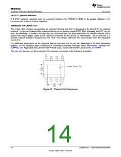
The exposed thermal pad dimensions for this package are shown in the following illustration.
Figure 17. Thermal Pad Dimensions
14
Copyright © 2013, Texas Instruments Incorporated
Product Folder Links :TPS56528

 TI [ TEXAS INSTRUMENTS ]