TPS562212
ZHCSNA3 –OCTOBER 2021
www.ti.com.cn
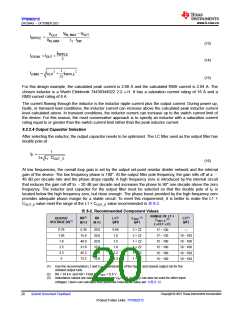
(4) COUT is the sum of nominal output capacitance. 22-μF, 0805, 10-V or higher specifications
capacitors are recommended.
(5) COUT_E is the effective value after derating. The value of L1 × COUT_E is recommended to be within
the range.
(6) R6 and C7 can be used to improve the load transient response and improve the loop-phase margin.
The capacitor value and ESR determine the amount of output voltage ripple. The device is intended for use with
ceramic or other low-ESR capacitors. Use 方程式 17 to determine the required RMS current rating for the output
capacitor.
VOUT ∂(V
- VOUT )
IN_MAX
ICORMS
=
12 ∂ VIN_MAX ∂L1 ∂ fSW
(17)
Two Murata GRM21BR61C226ME44L 22-μF, 0805, 16-V output capacitors are used for this design. From the
data sheet, the estimated DC derating rate is 66.8% at room temperature with AC voltage of 0.2 V. The total
output effective capacitance is approximately 14.7 μF. The value of L1 × COUT_E is 33 μH × μF, which is within
the recommended range.
8.2.2.5 Input Capacitor Selection
The device requires an input decoupling capacitor. A bulk capacitor is needed depending on the application. TI
recommends a ceramic capacitor over 10 μF for the decoupling capacitor. An additional 0.1-μF capacitor (C3)
from the VIN pin to ground is recommended to provide additional high frequency filtering. The capacitor voltage
rating needs to be greater than the maximum input voltage. The capacitor must also have a ripple current rating
greater than the maximum input current ripple of the device. The input ripple current can be calculated using 方
程式18.
V
IN_MIN - VOUT
VOUT
ICIRMS = IOUT
∂
∂
V
V
IN_MIN
IN_MIN
(18)
The value of a ceramic capacitor varies significantly over temperature and the amount of DC bias applied to the
capacitor. The capacitance variations due to temperature can be minimized by selecting a dielectric material that
is stable over temperature. X5R and X7R ceramic dielectrics are usually selected for power regulator capacitors
because they have a high capacitance-to-volume ratio and are fairly stable over temperature. The output
capacitor must also be selected with the DC bias taken into account. The capacitance value of a capacitor
decreases as the DC bias across a capacitor increases. For this example design, a ceramic capacitor with at
least a 25-V voltage rating is required to support the maximum input voltage. For this design, one Murata
GRM21BR61E226ME44L (10-μF, 25-V, 0805, X5R) capacitor has been selected. The effective capacitance
under input voltage of 12 V is 0.18 × 22 = 4 μF. The input capacitance value determines the input ripple voltage
of the regulator. The input voltage ripple can be calculated using 方程式 19. Using the design example values,
IOUT_MAX = 2 A, CIN_E = 4 μF, and fSW = 1.2 MHz, yield an input voltage ripple of 125 mV and a RMS input ripple
current of 0.47 A.
IOUT _MAX ∂ 0.25
DV
=
+ (IOUT _MAX ∂RESR _MAX )
IN
CIN ∂ fSW
(19)
where
• RESR_MAX = Maximum series resistance of the input capacitor
8.2.2.6 Bootstrap Capacitor Selection
A 0.1-μF ceramic capacitor must be connected between the BOOT to SW pin for proper operation. TI
recommends to use a ceramic capacitor with X5R or better grade dielectric. The capacitor must have a 10-V or
higher voltage rating.
Copyright © 2021 Texas Instruments Incorporated
Submit Document Feedback
21
Product Folder Links: TPS562212

 TI [ TEXAS INSTRUMENTS ]