TPS54560
SLVSBN0 –MARCH 2013
www.ti.com
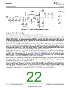
Bootstrap Capacitor Selection
A 0.1-μF ceramic capacitor must be connected between the BOOT and SW pins for proper operation. A ceramic
capacitor with X5R or better grade dielectric is recommended. The capacitor should have a 10 V or higher
voltage rating.
Undervoltage Lockout Set Point
The Undervoltage Lockout (UVLO) can be adjusted using an external voltage divider on the EN pin of the
TPS54560. The UVLO has two thresholds, one for power up when the input voltage is rising and one for power
down or brown outs when the input voltage is falling. For the example design, the supply should turn on and start
switching once the input voltage increases above 6.5 V (UVLO start). After the regulator starts switching, it
should continue to do so until the input voltage falls below 5 V (UVLO stop).
Programmable UVLO threshold voltages are set using the resistor divider of RUVLO1 and RUVLO2 between Vin and
ground connected to the EN pin. Equation 2 and Equation 3 calculate the resistance values necessary. For the
example application, a 442 kΩ between VIN and EN (RUVLO1) and a 90.9 kΩ between EN and ground (RUVLO2) are
required to produce the 6.5 V and 5 V start and stop voltages.
(38)
V
1.2 V
6.5 V - 1.2 V
442 kW
ENA
R
=
=
= 90.9 kW
UVLO2
V
- V
ENA
START
+1.2 mA
+ I
1
R
UVLO1
(39)
Output Voltage and Feedback Resistors Selection
The voltage divider of R5 and R6 sets the output voltage. For the example design, 10.2 kΩ was selected for R6.
Using Equation 1, R5 is calculated as 53.5 kΩ. The nearest standard 1% resistor is 53.6 kΩ. Due to the input
current of the FB pin, the current flowing through the feedback network should be greater than 1 μA to maintain
the output voltage accuracy. This requirement is satisfied if the value of R6 is less than 800 kΩ. Choosing higher
resistor values decreases quiescent current and improves efficiency at low output currents but may also
introduce noise immunity problems.
VOUT - 0.8 V
5 V - 0.8 V
æ
ö
RHS = RLS
x
= 10.2 kW x
= 53.5 kW
ç
÷
0.8 V
0.8 V
è
ø
(40)
Compensation
There are several methods to design compensation for DC-DC regulators. The method presented here is easy to
calculate and ignores the effects of the slope compensation that is internal to the device. Since the slope
compensation is ignored, the actual crossover frequency will be lower than the crossover frequency used in the
calculations. This method assumes the crossover frequency is between the modulator pole and the ESR zero
and the ESR zero is at least 10 times greater the modulator pole.
To get started, the modulator pole, ƒp(mod), and the ESR zero, ƒz1 must be calculated using Equation 41 and
Equation 42. For COUT, use a derated value of 87.4 μF. Use equations Equation 43 and Equation 44 to estimate
a starting point for the crossover frequency, ƒco. For the example design, ƒp(mod) is 1821 Hz and ƒz(mod) is 1100
kHz. Equation 42 is the geometric mean of the modulator pole and the ESR zero and Equation 44 is the mean of
modulator pole and half of the switching frequency. Equation 43 yields 44.6 kHz and Equation 44 gives 19.1 kHz.
Use the geometric mean value of Equation 43 and Equation 44 for an initial crossover frequency. For this
example, after lab measurement, the crossover frequency target was increased to 30 kHz for an improved
transient response.
Next, the compensation components are calculated. A resistor in series with a capacitor is used to create a
compensating zero. A capacitor in parallel to these two components forms the compensating pole.
IOUT max
(
)
5 A
fP mod
=
=
2´ p´ VOUT ´ COUT 2 ´ p ´ 5 V ´ 87.4 mF
= 1821 Hz
(
)
(41)
(42)
1
1
f
=
=
= 1100 kHz
Z mod
(
)
2´ p´R
´ C
2 ´ p ´ 1.67 mW ´ 87.4 mF
ESR
OUT
26
Submit Documentation Feedback
Copyright © 2013, Texas Instruments Incorporated
Product Folder Links: TPS54560

 TI [ TEXAS INSTRUMENTS ]