TPS51211
SLUSAA7 –NOVEMBER 2010
www.ti.com
UNIT
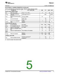
ELECTRICAL CHARACTERISTICS
over recommended free-air temperature range, V5IN=5V. (Unless otherwise noted)
PARAMETER
TEST CONDITIONS
MIN
TYP
MAX
SUPPLY CURRENT
TA = 25°C, No Load,
VEN = 5 V, VVFB = 0.735 V
IV5IN
V5IN supply current
320
600
1
mA
mA
IV5INSDN
V5IN shutdown current
TA = 25°C, No Load, VEN = 0 V
INTERNAL REFERENCE VOLTAGE
TA = 25°C
0.7005 0.7040 0.7075
VVFB
IVFB
VFB regulation voltage
VFB input current
V
–10°C ≤ TA ≤ 85°C
VVFB = 0.735 V, TA = 25°C
0.697
0.704
0.01
0.711
0.2
mA
OUTPUT DISCHARGE
Output discharge current from
SW pin
OUTPUT DRIVERS
IDischg
VEN = 0 V, VSW = 0.5 V
5
13
mA
Source, IDRVH = –50 mA
Sink, IDRVH = 50 mA
Source, IDRVL = –50 mA
Sink, IDRVL = 50 mA
1.5
0.7
1.0
0.5
17
3.6
2.0
3.0
1.6
RDRVH
RDRVL
tD
DRVH resistance
Ω
DRVL resistance
Dead time
DRVH-off to DRVL-on
DRVL-off to DRVH-on
7
ns
10
22
BOOT STRAP SWITCH
VFBST
Forward voltage
VBST leakage current
VV5IN-VBST, IF = 10 mA, TA = 25°C
0.1
0.2
1.5
V
IVBSTLK
VVBST = 34.5 V, VSW = 28 V, TA = 25°C
0.01
mA
DUTY AND FREQUENCY CONTROL
tOFF(min)
tON(min)
SOFTSTART
tss
Minimum off-time
Minimum on-time
TA = 25°C
VIN = 28 V, VOUT = 0.7 V, TA = 25°C(1)
150
260
79
400
ns
Internal SS time
From VEN = high to VOUT = 95%
1
ms
POWERGOOD
PG in from lower
PG in from higher
PG hysteresis
92.5%
107.5%
2.5%
3
95%
97.5%
VTHPG
PG threshold
110% 112.5%
5%
6
7.5%
IPGMAX
tPGDEL
PG sink current
PG delay
VPGOOD = 0.5 V
Delay for PG in
mA
ms
0.8
1
1.2
LOGIC THRESHOLD AND SETTING CONDITIONS
Enable
1.8
VEN
EN voltage threshold
V
Disable
0.5
1.0
IEN
EN input current
VEN = 5V
TA = 25°C(2)
mA
fSW
Switching frequency
266
290
314
kHz
(1) Ensured by design. Not production tested.
(2) Not production tested. Test condition is VIN= 8 V, VOUT= 1.1 V, IOUT = 10 A using application circuit shown in Figure 18.
4
Submit Documentation Feedback
Copyright © 2010, Texas Instruments Incorporated

 TI [ TEXAS INSTRUMENTS ]