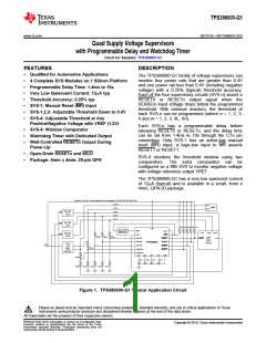
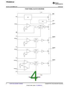
TPS386000-Q1
SBVS149 –SEPTEMBER 2010
www.ti.com
This integrated circuit can be damaged by ESD. Texas Instruments recommends that all integrated circuits be handled with
appropriate precautions. Failure to observe proper handling and installation procedures can cause damage.
ESD damage can range from subtle performance degradation to complete device failure. Precision integrated circuits may be more
susceptible to damage because very small parametric changes could cause the device not to meet its published specifications.
ORDERING INFORMATION(1)
TRANSPORT
PACKAGE-
LEAD
PACKAGE
TEMPERATURE
RANGE
PACKAGE
MARKING
MEDIA,
QUANTITY
PRODUCT
DESCRIPTION
DESIGNATOR(2)
Open-drain,
active low
TPS386000QRGPRQ1
VQFN-20
RGP
–40°C to +125°C
TPS386000Q
Reel, 3000
(1) For the most current package and ordering information see the Package Option Addendum at the end of this document, or see the TI
web site at www.ti.com.
(2) Package drawings, thermal data, and symbolization are available at www.ti.com/packaging.
ABSOLUTE MAXIMUM RATINGS(1)
Over operating junction temperature range, unless otherwise noted.
TPS386000-Q1
–0.3 to 7.0
UNIT
V
Input voltage range, VVCC
CT pin voltage range, VCT1, VCT2, VCT3, VCT4
–0.3 to VVCC + 0.3
V
Other voltage ranges: VRESET1, VRESET2, VRESET3, VRESET4, VMR, VSENSE1
VSENSE2, VSENSE3, VSENSE4L, VSENSE4H, VWDI, VWDO
,
–0.3 to 7.0
V
RESETn , RESETn, WDO, WDO, VREF pin current
Continuous total power dissipation
5
mA
See Thermal Information Table
–40 to +150
(2)
Operating virtual junction temperature range, TJ
°C
°C
°C
Operating ambient temperature range
Storage temperature range, TSTG
–40 to +125
–65 to +150
Latch-up performance meets 100mA per AEC-Q100
Class I
(1) Stresses beyond those listed under the Absolute Maximum Ratings may cause permanent damage to the device. These are stress
ratings only, and functional operation of the device at these or any other conditions beyond those indicated under the recommended
operating conditions is not implied. Exposure to absolute maximum rated conditions for extended periods may affect device reliability.
(2) As a result of the low dissipated power in this device, it is assumed that TJ = TA.
THERMAL INFORMATION
TPS386000-Q1
THERMAL METRIC(1)
RGP PACKAGE
UNITS
20 PINS
50.8
1.5
qJA
Junction-to-ambient thermal resistance
qJCtop
qJB
Junction-to-case (top) thermal resistance
Junction-to-board thermal resistance
21.0
42.8
8.8
°C/W
yJT
Junction-to-top characterization parameter
Junction-to-board characterization parameter
Junction-to-case (bottom) thermal resistance
yJB
qJCbot
21.2
(1) For more information about traditional and new thermal metrics, see the IC Package Thermal Metrics application report, SPRA953.
2
Submit Documentation Feedback
Copyright © 2010, Texas Instruments Incorporated
Product Folder Link(s): TPS386000-Q1

 TI [ TEXAS INSTRUMENTS ]