TPS1HC100-Q1
ZHCSLK6A –JULY 2021 –REVISED DECEMBER 2021
www.ti.com.cn
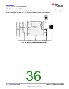
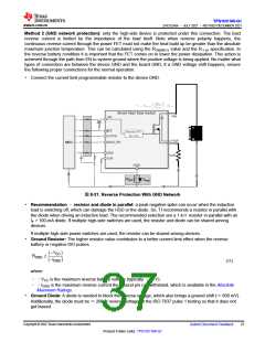
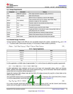
Method 2 (GND network protection): only the high-side device is protected under this connection. The load
reverse current is limited by the impedance of the load itself. Note when reverse polarity happens, the
continuous reverse current through the power FET must not make the heat build up be greater than the absolute
maximum junction temperature. This can be calculated using the RON(REV) value and the RθJA specification. In
the reverse battery condition it is important that the FET comes on to lower the power dissipation. This action is
achieved through the path from EN to system ground where the positive voltage is being applied. No matter what
types of connection are between the device GND and the board GND, if a GND voltage shift happens, ensure
the following proper connections for the normal operation:
• Connect the current limit programmable resistor to the device GND.
2
VBAT
T
=
R
R
B
5V
UT
MCU
d
RGND
DGND
图8-21. Reverse Protection With GND Network
• Recommendation –resistor and diode in parallel: a peak negative spike can occur when the inductive
load is switching off, which can damage the HSD or the diode. So, TI recommends a resistor in parallel with
the diode when driving an inductive load. The recommended selection are a 1-kΩresistor in parallel with an
IF > 100-mA diode. If multiple high-side switches are used, the resistor and diode can be shared among
devices.
If multiple high-side power switches are used, the resistor can be shared among devices.
• Ground Resistor: The higher resistor value contributes to a better current limit effect when the reverse
battery or negative ISO pulses.
œV
(
)
CC
RGND
í
œI
GND
(11)
where
– –VCC is the maximum reverse battery voltage (typically –16 V).
– –IGND is the maximum reverse current the ground pin can withstand, which is available in the Absolute
Maximum Ratings.
• Ground Diode: A diode is needed to block the reverse voltage, which also brings a ground shift (≈600 mV).
Additionally, the diode must be ≈200-V reverse voltage for the ISO 7637 pulse 1 testing so that it does not
get biased.
Copyright © 2022 Texas Instruments Incorporated
Submit Document Feedback
37
Product Folder Links: TPS1HC100-Q1

 TI [ TEXAS INSTRUMENTS ]