TPS1H100-Q1
www.ti.com.cn
ZHCSDD8D –OCTOBER 2014–REVISED DECEMBER 2019
Feature Description (continued)
12
11
10
9
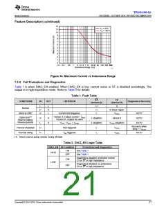
TA = 25°C
TA = 125°C
8
7
6
5
4
3
2
1
0
0.1 0.2
0.5
1
2 3 4 5 7 10 20 30 50 100 200 400
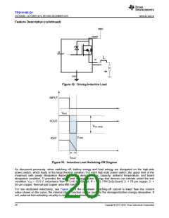
Inductance Range (mH)
D026
Figure 34. Maximum Current vs Inductance Range
7.3.4 Full Protections and Diagnostics
Table 1 is when DIAG_EN enabled. When DIAG_EN is low, current sense or ST is disabled accordingly. The
output is in high-impedance mode. Refer to Table 2 for details.
Table 1. Fault Table
ST
CS
(Version B)
CONDITIONS
IN
OUT
CRITERION
Diagnostics Recovery
(Version A)
L
H
H
L
H
L
H
H
L
0
Normal
In linear region
VCS,h
Short to GND
Current limit triggered.
AUTO
AUTO
AUTO
Open load(1)
Short to battery
Reverse polarity
Version A: Output current < Iol,on
Version B: Judged by users
H
L
H
H
L (deglitch)
Almost 0
VCS,h (deglitch)
VCS,h
VVS – VOUT < Vol,off
TSD triggered
Tsw triggered
L (deglitch)
Recovery when
temp < TSD,rst
Thermal shutdown
Thermal swing
H
H
L
L
VCS,h
AUTO
(1) Need external pullup resistor during off-state
Table 2. DIAG_EN Logic Table
DIAG_EN IN Condition
Protections and Diagnostics
See Table 1
See Table 1
ON
HIGH
OFF
Diagnostics disabled, protection normal
CS or ST is high Impedance
ON
LOW
Diagnostics disabled, no protections
CS or ST is high impedance
OFF
Copyright © 2014–2019, Texas Instruments Incorporated
21

 TI [ TEXAS INSTRUMENTS ]