ꢀ
ꢁꢂ
ꢃ
ꢄꢄ
ꢅ
ꢆꢇ
www.ti.com
SLOS407D − FEBRUARY 2003 − REVISED AUGUST 2004
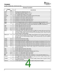
Terminal Functions
TERMINAL
I/O
DESCRIPTION
NO.
AGND
NAME
26
−
−
Analog ground for digital/analog cells in core
AV
AV
33
High-voltage analog power supply (8.5 V to 18 V)
5-V Regulated output capable of 100-mA output
CC
29
O
O
DD
AV REF
DD
7
5-V Reference output—provided for connection to adjacent VREF terminal.
BSLN
BSLP
BSRN
BSRP
COSC
FADE
13
I/O Bootstrap I/O for left channel, negative high-side FET
I/O Bootstrap I/O for left channel, positive high-side FET
I/O Bootstrap I/O for right channel, negative high-side FET
I/O Bootstrap I/O for right channel, positive high-side FET
24
48
37
28
I/O I/O for charge/discharging currents onto capacitor for ramp generator triangle wave biased at V2P5
30
I
Input for controlling volume ramp rate. A logic low on this pin places the amplifier in fade mode. A logic high on
this pin allows a quick transition to the desired volume setting when cycling SD or during power-up.
LINN
6
5
I
I
Negative differential audio input for left channel
Positive differential audio input for left channel
Class-D 1/2-H-bridge negative output for left channel
Class-D 1/2-H-bridge positive output for left channel
LINP
LOUTN
LOUTP
MODE
16, 17
20, 21
34
O
O
I
Input for MODE control. A logic high on this pin places the amplifier in the variable output mode and the Class-D
outputs are disabled. A logic low on this pin places the amplifier in the Class-D mode and Class-D stereo outputs
are enabled. Variable outputs (VAROUTL and VAROUTR) are still enabled in Class-D mode to be used as
line-level outputs for external amplifiers.
MODE_OUT
35
O
Output for control of the variable output amplifiers. When the MODE pin (34) is a logic high, the MODE_OUT
pin is driven low. When the MODE pin (34) is a logic low, the MODE_OUT pin is driven high. This pin is intended
for MUTE control of an external headphone amplifier. Leave unconnected when not used for headphone
amplifiercontrol.
PGNDL
PGNDR
PVCCL
PVCCL
PVCCR
PVCCR
REFGND
18, 19
42, 43
14, 15
22, 23
38,39
46, 47
12
−
−
−
−
−
−
−
Power ground for left channel H-bridge
Power ground for right channel H-bridge
Power supply for left channel H-bridge (tied to pins 22 and 23 internally), not connected to PVCCR or AV
Power supply for left channel H-bridge (tied to pins 14 and 15 internally), not connected to PVCCR or AV
Power supply for right channel H-bridge (tied to pins 46 and 47 internally), not connected to PVCCL or AV
Power supply for right channel H-bridge (tied to pins 38 and 39 internally), not connected to PVCCL or AV
.
.
.
.
CC
CC
CC
CC
Ground for gain control circuitry. Connect to AGND. If using a DAC to control the volume, connect the DAC
ground to this terminal.
RINP
3
2
I
I
Positive differential audio input for right channel
Negative differential audio input for right channel
RINN
ROSC
ROUTN
ROUTP
SD
27
I/O Current setting resistor for ramp generator. Nominally equal to 1/8*V
CC
44, 45
40, 41
1
O
O
I
Class-D 1/2-H-bridge negative output for right channel
Class-D 1/2-H-bridge positive output for right channel
Shutdown signal for IC (low = shutdown, high = operational). TTL logic levels with compliance to V
.
CC
VARDIFF
9
I
DC voltage to set the difference in gain between the Class-D and VAROUT outputs. Connect to GND or
AV REF if VAROUT outputs are unconnected.
DD
VARMAX
10
31
I
DC voltage that sets the maximum gain for the VAROUT outputs. Connect to GND or AV REF if VAROUT
DD
outputs are unconnected.
VAROUTL
O
Variable output for left channel audio. Line level output for driving external HP amplifier.
4

 TI [ TEXAS INSTRUMENTS ]