TPA152
75-mW STEREO AUDIO POWER AMPLIFIER
SLOS210A – JUNE 1998 – REVISED MARCH 2000
APPLICATION INFORMATION
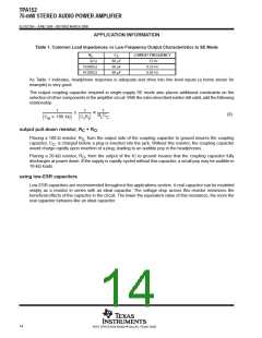
Table 1. Common Load Impedances vs Low Frequency Output Characteristics in SE Mode
R
C
LOWEST FREQUENCY
L
C
32 Ω
10,000 Ω
47,000 Ω
68 µF
68 µF
68 µF
73 Hz
0.23 Hz
0.05 Hz
As Table 1 indicates, headphone response is adequate and drive into line level inputs (a home stereo for
example) is very good.
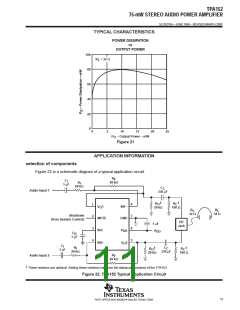
The output coupling capacitor required in single-supply SE mode also places additional constraints on the
selection of other components in the amplifier circuit. With the rules described earlier still valid, add the following
relationship:
1
1
1
(8)
R C
C
160 kΩ
C R
I
L C
B
I
output pull-down resistor, R + R
C
O
Placing a 100-Ω resistor, R , from the output side of the coupling capacitor to ground insures the coupling
C
capacitor, C , is charged before a plug is inserted into the jack. Without this resistor, the coupling capacitor
C
would charge rapidly upon insertion of a plug, leading to an audible pop in the headphones.
Placing a 20-kΩ resistor, R , from the output of the IC to ground insures that the coupling capacitor fully
O
discharges at power down. If the supply is rapidly cycled without this capacitor, a small pop may be audible in
10-kΩ loads.
using low-ESR capacitors
Low-ESR capacitors are recommended throughout this applications section. A real capacitor can be modeled
simply as a resistor in series with an ideal capacitor. The voltage drop across this resistor minimizes the
beneficial effects of the capacitor in the circuit. The lower the equivalent value of this resistance, the more the
real capacitor behaves like an ideal capacitor.
14
POST OFFICE BOX 655303 • DALLAS, TEXAS 75265

 TI [ TEXAS INSTRUMENTS ]