TPA152
75-mW STEREO AUDIO POWER AMPLIFIER
SLOS210A – JUNE 1998 – REVISED MARCH 2000
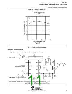
APPLICATION INFORMATION
power supply decoupling, C
S
The TPA152 is a high-performance CMOS audio amplifier that requires adequate power supply decoupling to
ensure that the output total harmonic distortion (THD) is as low as possible. Power supply decoupling also
prevents oscillations for long lead lengths between the amplifier and the speaker. The optimum decoupling is
achieved by using two capacitors of different types that target different types of noise on the power supply leads.
For higher frequency transients, spikes, or digital hash on the line, a good low equivalent-series-resistance
(ESR) ceramic capacitor, typically 0.1 µF, placed as close as possible to the device V
filtering lower-frequency noise signals, a larger aluminum electrolytic capacitor of 10 µF or greater placed near
lead, works best. For
DD
the power amplifier is recommended.
midrail bypass capacitor, C
B
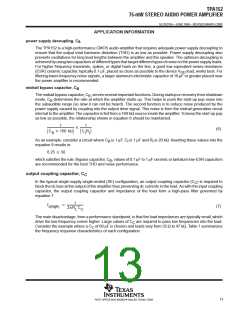
The midrail bypass capacitor, C , serves several important functions. During startup or recovery from shutdown
B
mode, C determines the rate at which the amplifier starts up. This helps to push the start-up pop noise into
B
the subaudible range (so slow it can not be heard). The second function is to reduce noise produced by the
power supply caused by coupling into the output drive signal. This noise is from the midrail generation circuit
internal to the amplifier. The capacitor is fed from a 160-kΩ source inside the amplifier. To keep the start-up pop
as low as possible, the relationship shown in equation 6 should be maintained.
1
1
(6)
C
160 kΩ
C R
I
B
I
As an example, consider a circuit where C is 1 µF, C is 1 µF and R is 20 kΩ. Inserting these values into the
B
I
I
equation 9 results in:
6.25 50
which satisfies the rule. Bypass capacitor, C , values of 0.1 µF to 1 µF ceramic or tantalum low-ESR capacitors
B
are recommended for the best THD and noise performance.
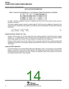
output coupling capacitor, C
C
In the typical single-supply single-ended (SE) configuration, an output coupling capacitor (C ) is required to
C
block the dc bias at the output of the amplifier thus preventing dc currents in the load. As with the input coupling
capacitor, the output coupling capacitor and impedance of the load form a high-pass filter governed by
equation 7.
1
2 R C
f
(7)
c(high)
L
C
The main disadvantage, from a performance standpoint, is that the load impedances are typically small, which
drive the low-frequency corner higher. Large values of C are required to pass low frequencies into the load.
C
Consider the example where a C of 68 µF is chosen and loads vary from 32 Ω to 47 kΩ. Table 1 summarizes
C
the frequency response characteristics of each configuration.
13
POST OFFICE BOX 655303 • DALLAS, TEXAS 75265

 TI [ TEXAS INSTRUMENTS ]