TPA152
75-mW STEREO AUDIO POWER AMPLIFIER
SLOS210A – JUNE 1998 – REVISED MARCH 2000
APPLICATION INFORMATION
gain setting resistors, R and R
F
I
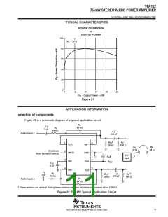
The gain for the TPA152 is set by resistors R and R according to equation 1.
F
I
R
F
Gain
(1)
R
I
Given that the TPA152 is a MOS amplifier, the input impedance is very high, consequently input leakage
currents are not generally a concern although noise in the circuit increases as the value of R increases. In
F
addition, a certain range of R values are required for proper start-up operation of the amplifier. Taken together
F
it is recommended that the effective impedance seen by the inverting node of the amplifier be set between 5
kΩ and 20 kΩ. The effective impedance is calculated in equation 2.
R R
F I
Effective Impedance
(2)
R
R
F
I
As an example, consider an input resistance of 20 kΩ and a feedback resistor of 20 kΩ. The gain of the amplifier
would be –1 and the effective impedance at the inverting terminal would be 10 kΩ, which is within the
recommended range.
For high performance applications, metal film resistors are recommended because they tend to have lower
noise levels than carbon resistors. For values of R above 50 kΩ, the amplifier tends to become unstable due
F
to a pole formed from R and the inherent input capacitance of the MOS input structure. For this reason, a small
F
compensation capacitor of approximately 5 pF should be placed in parallel with R . This, in effect, creates a
F
low-pass filter network with the cutoff frequency defined in equation 3.
1
2 R C
f
(3)
c(lowpass)
F
F
For example if R is 100 kΩ and C is 5 pF then f is 318 kHz, which is well outside the audio range.
co(lowpass)
F
F
input capacitor, C
I
In the typical application, an input capacitor, C , is required to allow the amplifier to bias the input signal to the
I
proper dc level for optimum operation. In this case, C and R form a high-pass filter with the corner frequency
I
I
determined in equation 4.
1
f
(4)
c(highpass)
2 R C
I
I
The value of C is important to consider as it directly affects the bass (low frequency) performance of the circuit.
I
Consider the example where R is 20 kΩ and the specification calls for a flat bass response down to 20 Hz.
I
Equation 4 is reconfigured as equation 5.
1
C
(5)
I
2 R f
c(highpass)
I
In this example, C is 0.40 µF, so one would likely choose a value in the range of 0.47 µF to 1 µF. A further
I
consideration for this capacitor is the leakage path from the input source through the input network (R , C ) and
I
I
thefeedbackresistor(R )totheload. Thisleakagecurrentcreatesadcoffsetvoltageattheinputtotheamplifier
F
that reduces useful headroom, especially in high-gain applications (> 10). For this reason a low-leakage
tantalum or ceramic capacitor is the best choice. When polarized capacitors are used, the positive side of the
capacitor should face the amplifier input in most applications, as the dc level there is held at V /2, which is
DD
likely higher that the source dc level. Please note that it is important to confirm the capacitor polarity in the
application.
12
POST OFFICE BOX 655303 • DALLAS, TEXAS 75265

 TI [ TEXAS INSTRUMENTS ]