TPA005D02
2-W STEREO CLASS-D AUDIO POWER AMPLIFIER
SLOS227C – AUGUST 1998 – REVISED MARCH 2000
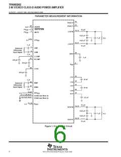
Class-D amplifier faults
Table 1. Amplifier Fault Table
†
†
FAULT 0
FAULT 1
DESCRIPTION
1
1
1
0
No fault—The device is operating normally.
Charge pump under-voltage lock-out (VCP-UV) fault—All low-side transistors are turned on, shorting the load to
ground. Once the charge pump voltage is restored, normal operation resumes, but FAULT1 is still active. FAULT1 is
cleared by cycling MUTE, SHUTDOWN, or the power supply.
0
0
Thermal fault—All the low-side transistors are turned on, shorting the load to ground. Once the junction temperature
drops 20°C, normal operation resumes. But the FAULTx terminals are still set and are cleared by cycling MUTE,
SHUTDOWN, or the power supply.
†
These logic levels assume a pull up to PV
DD
from the open-drain outputs.
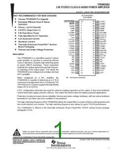
AVAILABLE OPTIONS
PACKAGED DEVICES
†
T
A
TSSOP
(DCA)
–40°C to 125°C
TPA005D02DCA
†
The DCA package is available in left-ended tape and reel. To order
a taped and reeled part, add the suffix R to the part number (e.g.,
TPA005D02DCAR).
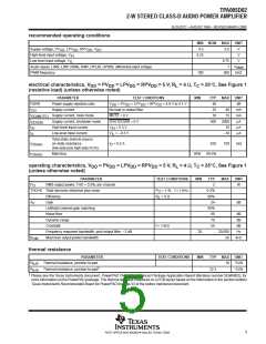
absolute maximum ratings over operating free-air temperature range, T = 25°C (unless otherwise
C
‡
noted)
Supply voltage, V
(PV , LPV , RPV , V ) . . . . . . . . . . . . . . . . . . . . . . . . . . . . . . . . . . . . . . . . . . . 5.5 V
DD DD DD DD
DD
Bias voltage (LSBIAS) . . . . . . . . . . . . . . . . . . . . . . . . . . . . . . . . . . . . . . . . . . . . . . . . . . . . . . . . . . . . . . . 12 V to 20 V
Input voltage, V (SHUTDOWN, MUTE, MODE) . . . . . . . . . . . . . . . . . . . . . . . . . . . . . . . . . . . . . . . –0.3 V to 5.8 V
I
Output current, I (FAULT0, FAULT1), open drain terminated . . . . . . . . . . . . . . . . . . . . . . . . . . . . . . . . . . . 1 mA
O
Charge pump voltage, V
. . . . . . . . . . . . . . . . . . . . . . . . . . . . . . . . . . . . . . . . . . . . . . . . . . . . . . . . . . PV
+ 20 V
CP
DD
Continuous H-bridge output current . . . . . . . . . . . . . . . . . . . . . . . . . . . . . . . . . . . . . . . . . . . . . . . . . . . . . . . . . . . 2 A
Pulsed H-Bridge output current, each output, I
(see Note 1) . . . . . . . . . . . . . . . . . . . . . . . . . . . . . . . . . . . 5 A
max
§
Continuous total power dissipation, T = 25°C . . . . . . . . . . . . . . . . . . . . . . . . . . . . . . . . . . . . . . . . . . . . . . . 4.5 W
C
Operating virtual junction temperature range, T . . . . . . . . . . . . . . . . . . . . . . . . . . . . . . . . . . . . . –40°C to 150°C
J
Operating case temperature range, T
. . . . . . . . . . . . . . . . . . . . . . . . . . . . . . . . . . . . . . . . . . . . . –40°C to 125°C
C
Storage temperature range, T
. . . . . . . . . . . . . . . . . . . . . . . . . . . . . . . . . . . . . . . . . . . . . . . . . . . –65°C to 150°C
stg
Lead temperature 1,6 mm (1/16 inch) from case for 10 seconds . . . . . . . . . . . . . . . . . . . . . . . . . . . . . . . 260°C
†
§
Stresses beyond those listed under “absolute maximum ratings” may cause permanent damage to the device. These are stress ratings only, and
functional operation of the device at these or any other conditions beyond those indicated under “recommended operating conditions” is not
implied. Exposure to absolute-maximum-rated conditions for extended periods may affect device reliability.
Thermal shutdown activates when T = 125°C.
J
NOTE 1: Pulse duration = 10 ms, duty cycle
2%
DISSIPATION RATING TABLE
DERATING FACTOR = 70°C
¶
T
≤ 25°C
T
A
T
A
= 85°C
T = 125°C
A
A
PACKAGE
POWER RATING
ABOVE T = 25°C
POWER RATING POWER RATING POWER RATING
A
DCA
5.6 W
44.8 mW/°C
3.6 W 2.9 W 1.1 W
¶
Please see the Texas Instruments document, PowerPAD Thermally Enhanced Package Application Report (literature number
SLMA002), for more information on the PowerPAD package. The thermal data was measured on a PCB layout based on the
information in the section entitled Texas Instruments Recommended Board for PowerPAD on page 33 of the before mentioned
document.
4
POST OFFICE BOX 655303 • DALLAS, TEXAS 75265

 TI [ TEXAS INSTRUMENTS ]