TPA005D02
2-W STEREO CLASS-D AUDIO POWER AMPLIFIER
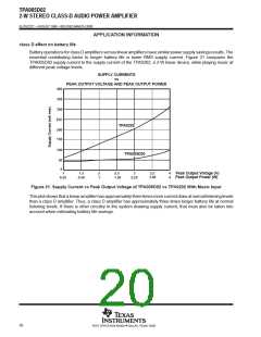
SLOS227C – AUGUST 1998 – REVISED MARCH 2000
APPLICATION INFORMATION
the ideal class D amplifier (continued)
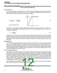
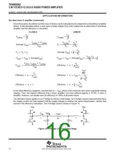
Giventheseplots, theefficiencyoftheclassDdevicecanbecalculatedandcomparedtoanideallinearamplifier
device. In the derivation below, a sine wave of peak voltage (V ) is the output from an ideal class D and linear
P
amplifier and the efficiency is calculated.
CLASS D
LINEAR
V
V
P
P
V
V
P
L(rms)
L(rms)
V
2
2
2
2
V
I
V
L(rms)
L(rms)
L(rms)
P
Average I
DD
L
V
R
L
2 R
L
DD
V
2
P
P
P
V
I
Average I
L
L
L
DD
R
L
V
V
DD
R
P
2
V
Average I
P
V
Average I
SUP
DD
DD
SUP
DD
DD
L
V
I
V
P
L
DD
L(rms)
L(rms)
P
Efficiency
SUP
V
P
DD
SUP
V 2
P
2R
P
L
L
Efficiency
Efficiency
Efficiency
Efficiency
V
DD
P
V
SUP
2
P
R
L
V
P
1
4
V
DD
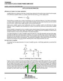
In the ideal efficiency equations, assume that V = V , which is the maximum sine wave magnitude without
P
DD
clipping. Then, the highest efficiency that a linear amplifier can have without clipping is 78.5%. A class D
amplifier, however, can ideally have an efficiency of 100% at all power levels.
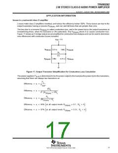
The derivation above applies to an H-bridge as well as a half-bridge. An H-bridge requires approximately twice
the supply current but only requires half the supply voltage to achieve the same output power—factors that
cancel in the efficiency calculation. The H-bridge circuit is shown in Figure 16.
V
DD
V
DD
M1
M4
I
L
I
OUT
V
OUT
+
–
V
A
L
L
R
L
C
C
L
L
M3
M2
Figure 16. H-Bridge Class D Output Stage
16
POST OFFICE BOX 655303 • DALLAS, TEXAS 75265

 TI [ TEXAS INSTRUMENTS ]