TPA005D02
2-W STEREO CLASS-D AUDIO POWER AMPLIFIER
SLOS227C – AUGUST 1998 – REVISED MARCH 2000
APPLICATION INFORMATION
efficiency of class D vs linear operation
Amplifier efficiency is defined as the ratio of output power delivered to the load to power drawn from the supply.
In the efficiency equation below, P is power across the load and P
is the supply power.
L
SUP
P
L
Efficiency
P
SUP
A high-efficiency amplifier has a number of advantages over one with lower efficiency. One of these advantages
is a lower power requirement for a given output, which translates into less waste heat that must be removed
from the device, smaller power supply required, and increased battery life.
Audio power amplifier systems have traditionally used linear amplifiers, which are well known for being
inefficient. Class D amplifiers were developed as a means to increase the efficiency of audio power amplifier
systems.
A linear amplifier is designed to act as a variable resistor network between the power supply and the load. The
transistors operate in their linear region and voltage that is dropped across the transistors (in their role as
variable resistors) is lost as heat, particularly in the output transistors.
The output transistors of a class D amplifier switch from full OFF to full ON (saturated) and then back again,
spending very little time in the linear region in between. As a result, very little power is lost to heat because the
transistors are not operated in their linear region. If the transistors have a low ON resistance, little voltage is
dropped across them, further reducing losses. The ideal class D amplifier is 100% efficient, which assumes that
both the ON resistance (R
) and the switching times of the output transistors are zero.
DS(ON)
the ideal class D amplifier
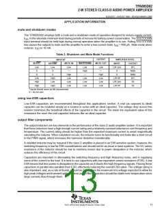
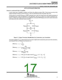
To illustrate how the output transistors of a class D amplifier operate, a half-bridge application is examined first
(Figure 13).
V
DD
M1
I
L
I
OUT
V
A
+
L
V
OUT
R
C
L
M2
C
L
–
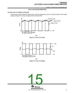
Figure 13. Half-Bridge Class D Output Stage
Figures 14 and 15 show the currents and voltages of the half-bridge circuit. When transistor M1 is on and M2
is off, the inductor current is approximately equal to the supply current. When M2 switches on and M1 switches
off, the supply current drops to zero, but the inductor keeps the inductor current from dropping. The additional
inductor current is flowing through M2 from ground. This means that V (the voltage at the drain of M2, as shown
A
in Figure 13) transitions between the supply voltage and slightly below ground. The inductor and capacitor form
a low-pass filter, which makes the output current equal to the average of the inductor current. The low pass filter
averages V , which makes V
equal to the supply voltage multiplied by the duty cycle.
A
OUT
14
POST OFFICE BOX 655303 • DALLAS, TEXAS 75265

 TI [ TEXAS INSTRUMENTS ]