TMS320 SECOND-GENERATION
DEVICES
SPRS010B — MAY 1987 — REVISED NOVEMBER 1990
instruction set summary
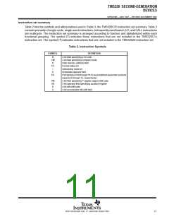
Table 2 lists the symbols and abbreviations used in Table 3, the TMS320C25 instruction set summary. Table 3
consists primarily of single-cycle, single-word instructions. Infrequently used branch, I/O, and CALL instructions
are multicycle. The instruction set summary is arranged according to function and alphabetized within each
†
functional grouping. The symbol ( ) indicates those instructions that are not included in the TMS320C1x
‡
instruction set. The symbol ( ) indicates instructions that are not included in the TMS32020 instruction set.
Table 2. Instruction Symbols
SYMBOL
DEFINITION
4-bit field specifying a bit code
2-bit field specifying compare mode
Data memory address field
B
CM
D
FO
I
Format status bit
Addressing mode bit
K
Immediate operand field
PA
Portaddress(PA0throughPA15arepredefinedassemblersymbols
equal to 0 through 15, respectively.)
2-bit field specifying P register output shift code
3-bit operand field specifying auxiliary register
4-bit left-shift code
PM
AR
S
X
3-bit accumulator left-shift field
POST OFFICE BOX 1443 • HOUSTON, TEXAS 77001
11

 TI [ TEXAS INSTRUMENTS ]