TMS320C6672
Multicore Fixed and Floating-Point Digital Signal Processor
SPRS708C—February 2012
www.ti.com
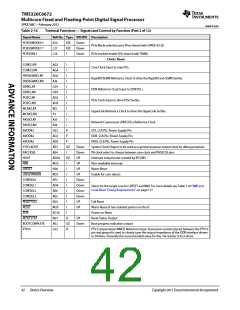
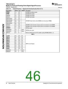
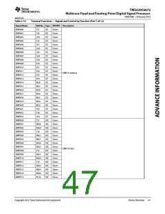
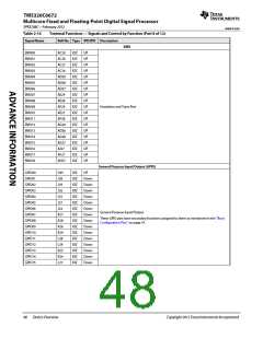
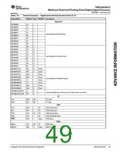
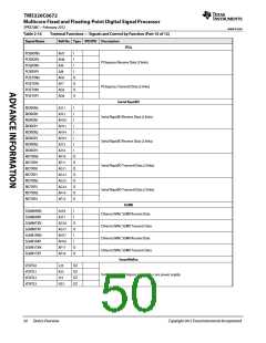
Table 2-16
Terminal Functions — Signals and Control by Function (Part 6 of 12)
Ball No. Type IPD/IPU Description
Signal Name
DDRRAS
C10
E12
D11
E18
A12
B12
A16
B16
D13
E13
E11
G27
H27
E14
OZ
OZ
OZ
OZ
OZ
OZ
OZ
OZ
OZ
OZ
OZ
I
DDR EMIF Row Address Strobe
DDR EMIF Write Enable
DDR EMIF Clock Enable
DDR EMIF Clock Enable
DDRWE
DDRCKE0
DDRCKE1
DDRCLKOUTP0
DDRCLKOUTN0
DDRCLKOUTP1
DDRCLKOUTN1
DDRODT0
DDR EMIF Output Clocks to drive SDRAMs (one clock pair per SDRAM)
DDR EMIF On Die Termination Outputs used to set termination on the SDRAMs
DDR EMIF On Die Termination Outputs used to set termination on the SDRAMs
DDR Reset signal
DDRODT1
DDRRESET
DDRSLRATE0
DDRSLRATE1
VREFSSTL
Down
Down
DDR Slew rate control
I
P
Reference Voltage Input for SSTL15 buffers used by DDR EMIF (VDDS15 ÷ 2)
EMIF16
EMIFRW
EMIFCE0
EMIFCE1
EMIFCE2
EMIFCE3
EMIFOE
P26
P25
R27
R28
R25
R26
P24
R24
R23
T29
T28
OZ
OZ
OZ
OZ
OZ
OZ
OZ
OZ
OZ
I
UP
UP
UP
UP
UP
UP
EMIF16 Control Signals
EMIFWE
UP
EMIFBE0
EMIFBE1
EMIFWAIT0
EMIFWAIT1
UP
UP
Down
Down
I
46
Device Overview
Copyright 2012 Texas Instruments Incorporated

 TI [ TEXAS INSTRUMENTS ]