TMS320C6672
Multicore Fixed and Floating-Point Digital Signal Processor
SPRS708C—February 2012
www.ti.com
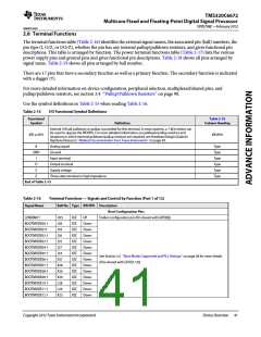
2.8 Terminal Functions
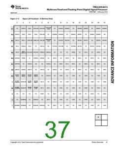
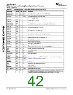
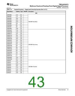
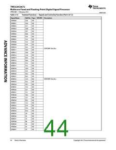
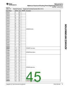
The terminal functions table (Table 2-16) identifies the external signal names, the associated pin (ball) numbers, the
pin type (I, O/Z, or I/O/Z), whether the pin has any internal pullup/pulldown resistors, and gives functional pin
descriptions. This table is arranged by function. The power terminal functions table (Table 2-17) lists the various
power supply pins and ground pins and gives functional pin descriptions. Table 2-18 shows all pins arranged by
signal name. Table 2-19 shows all pins arranged by ball number.
There are 17 pins that have a secondary function as well as a primary function. The secondary function is indicated
with a dagger (†).
For more detailed information on device configuration, peripheral selection, multiplexed/shared pins, and
pullup/pulldown resistors, see section 3.4 ‘‘Pullup/Pulldown Resistors’’ on page 90.
Use the symbol definitions in Table 2-15 when reading Table 2-16.
Table 2-15
I/O Functional Symbol Definitions
Functional
Symbol
Table 2-16
Column Heading
Definition
Internal 100-μA pulldown or pullup is provided for this terminal. In most systems, a 1-kΩ resistor can
be used to oppose the IPD/IPU. For more detailed information on pulldown/pullup resistors and
situations in which external pulldown/pullup resistors are required, see Hardware Design Guide for
KeyStone Devices in ‘‘Related Documentation from Texas Instruments’’ on page 69.
IPD or IPU
IPD/IPU
A
Analog signal
Type
Type
Type
Type
Type
Type
GND
Ground
I
Input terminal
O
Output terminal
Supply voltage
S
Z
Three-state terminal or high impedance
End of Table 2-15
Table 2-16
Signal Name
Terminal Functions — Signals and Control by Function (Part 1 of 12)
Ball No. Type IPD/IPU Description
Boot Configuration Pins
LENDIAN †
H25
J28
J29
J26
J25
J27
J24
K27
K28
K26
K29
L28
L29
K25
IOZ
IOZ
IOZ
IOZ
IOZ
IOZ
IOZ
IOZ
IOZ
IOZ
IOZ
IOZ
IOZ
IOZ
UP
Endian configuration pin (Pin shared with GPIO[0])
BOOTMODE00 †
BOOTMODE01†
BOOTMODE02 †
BOOTMODE03 †
BOOTMODE04 †
BOOTMODE05 †
BOOTMODE06 †
BOOTMODE07 †
BOOTMODE08 †
BOOTMODE09 †
BOOTMODE10 †
BOOTMODE11 †
BOOTMODE12 †
Down
Down
Down
Down
Down
Down
Down
Down
Down
Down
Down
Down
Down
See Section 2.5 ‘‘Boot Modes Supported and PLL Settings’’ on page 28 for more details
(Pins shared with GPIO[1:13])
Copyright 2012 Texas Instruments Incorporated
Device Overview 41

 TI [ TEXAS INSTRUMENTS ]