TMP451
www.ti.com
SBOS686 –JUNE 2013
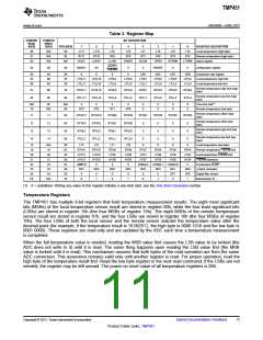
Table 3. Register Map
POINTER
READ
(HEX)
POINTER
WRITE
(HEX)
BIT DESCRIPTION
POR (HEX)
7
6
5
4
3
2
1
0
REGISTER DESCRIPTION
00
01
02
N/A
N/A
N/A
00
00
LT11
RT11
BUSY
LT10
RT10
LHIGH
LT9
LT8
LT7
LT6
LT5
LT4
Local temperature (high byte)
Remote temperature (high byte)
status register
RT9
LLOW
RT8
RT7
RT6
OPEN
RT5
RT4
N/A
RHIGH
RLOW
RTHRM
LTHRM
ALERT/
THERM2
03
09
00
MASK1
SD
0
0
RANGE
0
0
configuration register
04
05
06
0A
0B
0C
08
55
00
0
0
0
0
CR3
CR2
CR1
CR0
Conversion rate register
Local temperature high limit
Local temperature low limit
LTHL11
LTLL11
LTHL10
LTLL10
LTHL9
LTLL9
LTHL8
LTLL8
LTHL7
LTLL7
LTHL6
LTLL6
LTHL5
LTLL5
LTHL4
LTLL4
Remote temperature high limit (high
byte)
07
08
0D
0E
55
00
RTHL11
RTLL11
RTHL10
RTLL10
RTHL9
RTLL9
RTHL8
RTLL8
RTHL7
RTLL7
RTHL6
RTLL6
RTHL5
RTLL5
RTHL4
RTLL4
Remote temperature low limit (high
byte)
N/A
10
0F
N/A
00
X
X
X
X
X
0
X
0
X
0
X
0
One-shot start(1)
N/A
RT3
RT2
RT1
RT0
Remote temperature (low byte)
Remote temperature offset (high
byte)
11
12
13
14
11
12
13
14
00
00
00
00
RTOS11
RTOS3
RTHL3
RTLL3
RTOS10
RTOS2
RTHL2
RTLL2
RTOS9
RTOS1
RTHL1
RTLL1
RTOS8
RTOS0
RTHL0
RTLL0
RTOS7
RTOS6
RTOS5
RTOS4
Remote temperature offset (low
byte)
0
0
0
0
0
0
0
0
0
0
0
0
Remote temperature high limit (low
byte)
Remote temperature low limit (low
byte)
15
19
20
21
22
23
24
FE
N/A
19
00
6C
55
0A
01
00
00
55
LT3
RTH11
LTH11
HYS11
SMBTO
NC7
LT2
RTH10
LTH10
HYS10
0
LT1
RTH9
LTH9
HYS9
0
LT0
RTH8
LTH8
HYS8
0
0
RTH7
LTH7
HYS7
CONAL2
NC3
0
0
RTH6
LTH6
HYS6
CONAL1
NC2
0
0
RTH5
LTH5
HYS5
CONAL0
NC1
0
Local temperature (low byte)
Remote temperature THERM limit
Local temperature THERM limit
THERM hysteresis
RTH4
LTH4
HYS4
0
20
21
22
Consecutive ALERT
23
NC6
0
NC5
0
NC4
0
NC0
DF0
1
η-factor correction
24
0
DF1
Digital filter control
N/A
0
1
0
1
0
1
0
Manufacturer ID
(1) X = undefined. Writing any value to this register initiates a one-shot start; see the One-Shot Conversion section.
Temperature Registers
The TMP451 has multiple 8-bit registers that hold temperature measurement results. The eight most significant
bits (MSBs) of the local temperature sensor result are stored in register 00h, while the four least significant bits
(LSBs) are stored in register 15h (the four MSBs of register 15h). The eight MSBs of the remote temperature
sensor result are stored in register 01h, and the four LSBs are stored in register 10h (the four MSBs of register
10h). The four LSBs of both the local sensor and the remote sensor indicate the temperature value after the
decimal point (for example, if the temperature result is 10.0625˚C, the high byte is 0000 1010 and the low byte is
0001 0000). These registers are read-only and are updated by the ADC each time a temperature measurement
is completed.
When the full temperature value is needed, reading the MSB value first causes the LSB value to be locked (the
ADC does not write to it) until it is read. The same thing happens upon reading the LSB value first (the MSB
value is locked until it is read). This mechanism assures that both bytes of the read operation are from the same
ADC conversion. This assurance remains valid only until another register is read. For proper operation, read the
high byte of the temperature result first. Read the low byte register in the next read command; if the LSBs are not
needed, the register may be left unread. The power-on reset value of all temperature registers is 00h.
Copyright © 2013, Texas Instruments Incorporated
Submit Documentation Feedback
11
Product Folder Links: TMP451

 TI [ TEXAS INSTRUMENTS ]