TMP451
www.ti.com
SBOS686 –JUNE 2013
APPLICATION INFORMATION
The TMP451 is a digital temperature sensor that combines a local temperature measurement channel and a
remote-junction temperature measurement channel in a single DFN-8 package. The device is two-wire- and
SMBus-interface compatible, and is specified over a temperature range of –40°C to +125°C. The TMP451 also
contains multiple registers for programming and holding configuration settings, temperature limits, and
temperature measurement results.
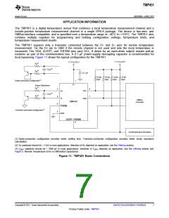
The TMP451 requires only a transistor connected between the D+ and D– pins for remote temperature
measurement. Tie the D+ pin to GND if the remote channel is not used and only the local temperature is
measured. The SDA, ALERT, and THERM pins (and SCL, if driven by an open-drain output) require pull-up
resistors as part of the communication bus. A 0.1-µF power-supply decoupling capacitor is recommended for
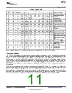
local bypassing. Figure 11 shows the typical configuration for the TMP451.
1.7 V to 3.6 V
1.7 V to 3.6 V
(2)
RS
(3)
CDIFF
(2)
RS
0.1 µF
10 kꢀ
(typ)
10 kꢀ
(typ)
10 kꢀ
(typ)
10 kꢀ
(typ)
Diode-connected configuration(1)
Series Resistance
1
V+
(2)
RS
2
3
4
5
8
7
D+
SCL
SDA
(3)
CDIFF
(2)
RS
D-
SMBus
Controller
TMP451
THERM
GND
Transistor-connected configuration(1)
ALERT / THERM2
6
Overtemperature Shutdown
(1) Diode-connected configuration provides better settling time. Transistor-connected configuration provides better series resistance
cancellation.
(2) RS (optional) should be < 1 kΩ in most applications. Selection of RS depends on application; see the Filtering section.
(3) CDIFF (optional) should be < 1000 pF in most applications. Selection of CDIFF depends on application; see the Filtering section and
Figure 5, Remote Temperature Error vs Differential Capacitance.
Figure 11. TMP451 Basic Connections
Copyright © 2013, Texas Instruments Incorporated
Submit Documentation Feedback
7
Product Folder Links: TMP451

 TI [ TEXAS INSTRUMENTS ]