TMP451
SBOS686 –JUNE 2013
www.ti.com
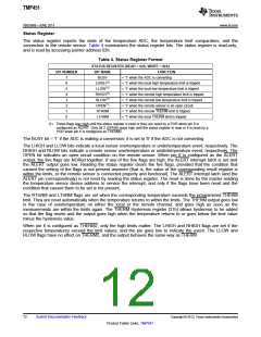
Status Register
The status register reports the state of the temperature ADC, the temperature limit comparators, and the
connection to the remote sensor. Table 4 summarizes the status register bits. The status register is read-only,
and is read by accessing pointer address 02h.
Table 4. Status Register Format
STATUS REGISTER (READ = 02h, WRITE = N/A)
BIT NUMBER
BIT NAME
BUSY
FUNCTION
7
6
5
4
3
2
1
0
= '1' when the ADC is converting
LHIGH(1)
LLOW(1)
RHIGH(1)
RLOW(1)
OPEN(1)
RTHRM
LTHRM
= '1' when the local high temperature limit is tripped
= '1' when the local low temperature limit is tripped
= '1' when the remote high temperature limit is tripped
= '1' when the remote low temperature limit is tripped
= '1' when the remote sensor is an open circuit
= '1' when the remote THERM limit is tripped
= '1' when the local THERM limit is tripped
(1) These flags stay high until the status register is read or they are reset by a POR when pin 6 is
configured as ALERT. Only bit 2 (OPEN) stays high until the status register is read or it is reset by a
POR when pin 6 is configured as THERM2.
The BUSY bit = '1' if the ADC is making a conversion; it is set to '0' if the ADC is not converting.
The LHIGH and LLOW bits indicate a local sensor overtemperature or undertemperature event, respectively. The
RHIGH and RLOW bits indicate a remote sensor overtemperature or undertemperature event, respectively. The
OPEN bit indicates an open circuit condition on the remote sensor. When pin 6 is configured as the ALERT
output, the five flags are NORed together. If any of the five flags are high, the ALERT interrupt latch is set and
the ALERT output goes low. Reading the status register clears the five flags, provided that the condition that
caused the setting of the flags is not present anymore (that is, the value of the corresponding result register is
within the limits, or the remote sensor is connected properly and functional). The ALERT interrupt latch (and the
ALERT pin correspondingly) is not reset by reading the status register. The reset is done by the master reading
the temperature sensor device address to service the interrupt, and only if the flags have been reset and the
condition that caused them to be set is not present.
The RTHRM and LTHRM flags are set when the corresponding temperature exceeds the programmed THERM
limit. They are reset automatically when the temperature returns to within the limits. The THERM output goes low
in the case of overtemperature on either the local or the remote channel, and goes high as soon as the
measurements are within the limits again. The THERM Hysteresis register (21h) allows hysteresis to be added
so that the flag resets and the output goes high when the temperature returns to or goes below the limit value
minus the hysteresis value.
When pin 6 is configured as THERM2, only the high limits matter. The LHIGH and RHIGH flags are set if the
respective temperatures exceed the limit values, and the pin goes low to indicate the event. The LLOW and
RLOW flags have no effect on THERM2, and the output behaves the same way as THERM.
12
Submit Documentation Feedback
Copyright © 2013, Texas Instruments Incorporated
Product Folder Links: TMP451

 TI [ TEXAS INSTRUMENTS ]