TMDS361
SLLS919–DECEMBER 2008............................................................................................................................................................................................ www.ti.com
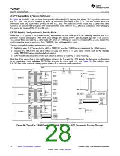
A DTV Supporting a Passive CEC Link
In Figure 34, the DTV does not have the capability of handling CEC signals, but allows CEC signals to pass over
the CEC bus. The source selection is done by the control command of the DTV. The user cannot force the
command from any audio/video product on the CEC bus. The selected source reads the E-EDID data after
receiving an asserted HPD signal. The microcontroller loads different CEC physical addresses while changing
the source by means of the S1 and S2 pins.
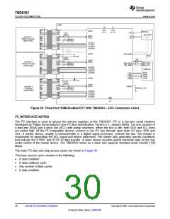
E-EDID Reading Configurations in Standby Mode
When the DTV system is in standby mode, the sources do not read the E-EDID memory because the 1-kΩ
pulldown resistor keeping the HPD_SINK input at logic low forces all HPD pins to output logic-low to all sources.
The source does not read the E-EDID data with a low on HPD signal. However, if reading the E-EDID data in the
system standby mode is preferred, then TMDS361 can still support this need.
The recommended configuration sequences are:
1. Apply the same 3.3-V power to the VCC of TMDS361 and the TMDS line termination at the HDMI receiver
2. Because the TMDS361 has clock-detect circuitry and there is no valid input TMDS clock in the standby
mode, TMDS361 draws significanty less current.
3. Set S1 and S2 to select the source port which is allowed to read the E-EDID memory.
Note that if the source has a time-out limitation between the 5-V and the HPD signals, the foregoing configuration
is not applicable. Uses individual EEPROMs assigned for each input port, see Figure 35. The solution uses
E-EDID data to be readable during system power-off or standby-mode operations.
SINK
HPD
5V
VCC
(3.3 V)
HPD
5V
VDD
(5 V)
HPD1
5V
47kW
EQ
mController
SDA1
SCL1
S1
S2
SDA
SDA
SCL
CEC
SCL
CEC
SOURCE 1
SOURCE 2
SOURCE 3
CEC
A11/B11
A12/B12
A13/B13
A14/B14
CLK
D0
CLK
D0
D1
D2
D1
D2
HPD
5V
HPD
5V
HPD2
HPD_SINK
3.3V
4.7kW 4.7kW
5V
47kW
1kW
SDA2
SCL2
SDA_SINK
SCL_SINK
DDC_SDA
DDC_SCL
SDA
SCL
CEC
SDA
SCL
CEC
CEC
E-EDID
A21/B21
A22/B22
A23/B23
A24/B24
CLK
D0
CLK
D 0
HDMI RX
Y1/Z1
Y2/Z2
Y3/Z3
Y4/Z4
Y1/Z1
Y2/Z2
Y3/Z3
Y4/Z4
D1
D2
D1
D2
HPD
5V
HPD
5V
HPD3
5V
47kW
VSADJ
SDA3
SCL3
SDA
SCL
CEC
SDA
SCL
CEC
4.02 kW 10%
CEC
A31/B31
A32/B32
A33/B33
A34/B34
CLK
D0
CLK
D0
D1
D2
D1
D2
GND
Figure 34. Three-Port HDMI-Enabled DTV With TMDS361 – CEC Commands Passing Through
28
Submit Documentation Feedback
Copyright © 2008, Texas Instruments Incorporated
Product Folder Link(s) :TMDS361

 TI [ TEXAS INSTRUMENTS ]