Circuit Description
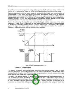
An additional comparator compares the voltage at the capacitor with the reference voltage and forces the
outputs into the active state as long as the voltage at the capacitor is lower than the reference voltage.
Figure 4 shows the timing of the various signals. In this example the SENSE input is connected to the
supply voltage Vcc as in typical applications of this device. The minimum supply voltage for which the
function of this device is guaranteed is 3.6V. After power-on the outputs are undefined until the minimum
supply voltage V is reached. For the TL77xxA the minimum supply voltage is V = 3.0 V (typical 2.5 V),
res
res
for the TL77xxB is Vres = 1.0 V. Also, when using the TL77xxB it has to be noted, that with such low supply
voltages the function of the reset input of the following circuit may not be guaranteed.
Beyond the voltage V the capacitor C is first kept discharged, and the outputs stay in the active
res
t
state(RESET = High, RESET = Low). When the input voltage becomes higher than the threshold voltage
Vt, the thyristor is turned off and the capacitor is charged. After a delay, t, the voltage at the capacitor
d
passes the trigger level of the output comparator and the outputs become inactive. The circuit to be
initialized is now set to a defined state and starts the correct operation.
Note: SENSE Input connected to Vcc
Figure 4. Timing diagram
The thyristor is triggered again during voltage drops below the threshold voltage V. and the reset
t
sequence starts again. Also now the outputs stays in the active state for the time dt after the return of the
supply voltage to its required value. A hysteresis V at the input comparator prevents oscillation of the input
h
circuit when the input voltage rises or falls slowly.
The time td - and also the capacitor C - are determined by the requirements of the following circuitry. In
t
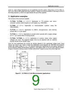
TTL or CMOS logic circuits, theoretically a reset time of 20 to 50ns is sufficient. For proper operation,
microcomputers require a reset signal which lasts for several machine cycles and is thus of the order of 10
to 200 ms, according to the type of microcomputer in use. In a practical application, the delay time will be
determined by characteristics of the power supply. Care has to be taken, that during and shortly after
4
Literature Number: SLVAE04

 TI [ TEXAS INSTRUMENTS ]