TAS5715
www.ti.com
SLOS645 –AUGUST 2010
Automatic Gain Limit (DRC)
The DRC scheme has a single programmable threshold. There is one ganged DRC for the high-band left/right
channels and one DRC for the low-band left/right channels.
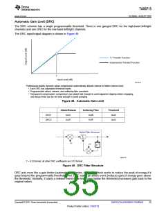
The DRC input/output diagram is shown in Figure 48.
1:1 Transfer Function
Implemented Transfer Function
T
Input Level (dB)
M0176-01
Professional-quality dynamic range compression automatically adjusts volume to flatten volume level.
• Each DRC has adjustable threshold levels.
• Programmable attack, release, and softening-filter constants
• Transparent compression: compressors can attack fast enough to avoid apparent clipping before engaging,
and decay times can be set slow enough to avoid pumping.
Figure 48. Automatic Gain Limit
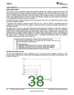
Attack/Release
0x3C
Softening Filter
0x3B
Threshold
0x40
DRC1
DRC2
0x3E
0x3F
0x43
Alpha Filter Structure
S
a
Z–1
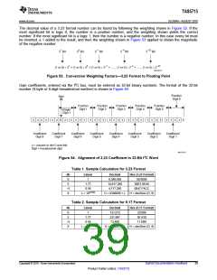
w
B0265-05
T = 9.23 format, all other DRC coefficients are 3.23 format
Figure 49. DRC Filter Structure
DRC acts more like a gain limiter (automatic gain limiter, AGL). The block works to reduce the peak of energy if it
goes beyond the programmable threshold level. DRC starts an attack event (reduces gain) if energy goes above
the threshold. Similarly, it starts a release event if the level goes below the threshold (increases gain back to the
original value).
Copyright © 2010, Texas Instruments Incorporated
Submit Documentation Feedback
35
Product Folder Link(s): TAS5715

 TI [ TEXAS INSTRUMENTS ]