TAS5715
SLOS645 –AUGUST 2010
www.ti.com
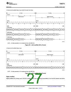
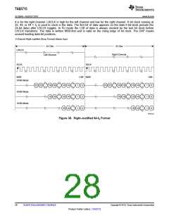
it is for the right channel. LRCLK is high for the left channel and low for the right channel. A bit clock running at
32, 48, or 64 × fS is used to clock in the data. The first bit of data appears on the data 8 bit-clock periods (for
24-bit data) after LRCLK toggles. In RJ mode the LSB of data is always clocked by the last bit clock before
LRCLK transitions. The data is written MSB-first and is valid on the rising edge of bit clock. The DAP masks
unused leading data-bit positions.
2-Channel Right-Justified (Sony Format) Stereo Input
32 Clks
32 Clks
LRCLK
SCLK
Right Channel
Left Channel
SCLK
MSB
LSB MSB
LSB
0
24-Bit Mode
23 22
19 18
19 18
15 14
15 14
15 14
1
1
1
0
23 22
19 18
19 18
15 14
15 14
15 14
1
1
1
20-Bit Mode
16-Bit Mode
0
0
0
0
T0034-03
Figure 38. Right-Justified 64-fS Format
28
Submit Documentation Feedback
Copyright © 2010, Texas Instruments Incorporated
Product Folder Link(s): TAS5715

 TI [ TEXAS INSTRUMENTS ]