TAS5727
SLOS670 –NOVEMBER 2010
www.ti.com
PWM LEVEL METER
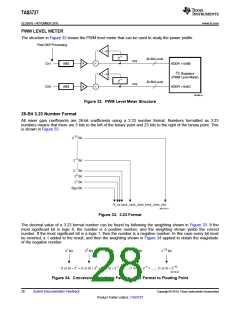
The structure in Figure 32 shows the PWM level meter that can be used to study the power profile.
Post-DAP Processing
1 – a
Z–1
32-Bit Level
rms
a
a
Ch1
Ch2
ABS
ABS
ADDR = 0x6B
I2C Registers
(PWM Level Meter)
1 – a
Z–1
32-Bit Level
rms
ADDR = 0x6C
B0396-01
Figure 32. PWM Level Meter Structure
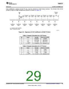
26-Bit 3.23 Number Format
All mixer gain coefficients are 26-bit coefficients using a 3.23 number format. Numbers formatted as 3.23
numbers means that there are 3 bits to the left of the binary point and 23 bits to the right of the binary point. This
is shown in Figure 33 .
2–23 Bit
2–5 Bit
2–1 Bit
20 Bit
21 Bit
Sign Bit
S_xx.xxxx_xxxx_xxxx_xxxx_xxxx_xxx
M0125-01
Figure 33. 3.23 Format
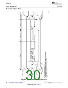
The decimal value of a 3.23 format number can be found by following the weighting shown in Figure 33. If the
most significant bit is logic 0, the number is a positive number, and the weighting shown yields the correct
number. If the most significant bit is a logic 1, then the number is a negative number. In this case every bit must
be inverted, a 1 added to the result, and then the weighting shown in Figure 34 applied to obtain the magnitude
of the negative number.
21 Bit
20 Bit
2–1 Bit
2–4 Bit
2–23 Bit
(1 or 0) ´ 21 + (1 or 0) ´ 20 + (1 or 0) ´ 2–1 + ....... (1 or 0) ´ 2–4 + ....... (1 or 0) ´ 2–23
M0126-01
Figure 34. Conversion Weighting Factors—3.23 Format to Floating Point
28
Submit Documentation Feedback
Copyright © 2010, Texas Instruments Incorporated
Product Folder Link(s): TAS5727

 TI [ TEXAS INSTRUMENTS ]