TAS5727
www.ti.com
SLOS670 –NOVEMBER 2010
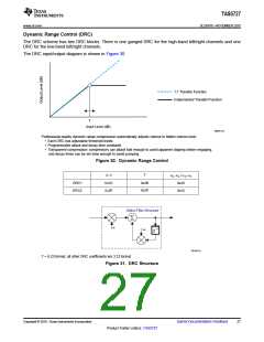
Dynamic Range Control (DRC)
The DRC scheme has two DRC blocks. There is one ganged DRC for the high-band left/right channels and one
DRC for the low-band left/right channels.
The DRC input/output diagram is shown in Figure 30.
1:1 Transfer Function
Implemented Transfer Function
T
Input Level (dB)
M0091-04
Professional-quality dynamic range compression automatically adjusts volume to flatten volume level.
• Each DRC has adjustable threshold levels.
• Programmable attack and decay time constants
• Transparent compression: compressors can attack fast enough to avoid apparent clipping before engaging,
and decay times can be set slow enough to avoid pumping.
Figure 30. Dynamic Range Control
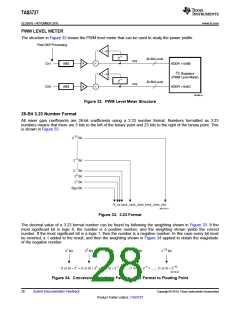
a, w
T
aa, wa / ad, wd
0x40
DRC1
DRC2
0x3C
0x3F
0x3B
0x3E
0x43
Alpha Filter Structure
S
a
Z–1
w
B0265-04
T = 9.23 format, all other DRC coefficients are 3.23 format
Figure 31. DRC Structure
Copyright © 2010, Texas Instruments Incorporated
Submit Documentation Feedback
27
Product Folder Link(s): TAS5727

 TI [ TEXAS INSTRUMENTS ]