Quick Setup Guide
www.ti.com
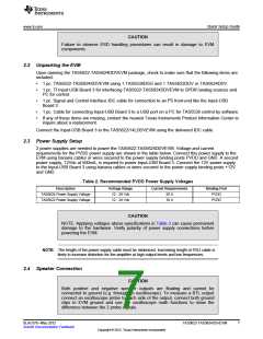
2.5 Output Configuration BTL and PBTL
When changing mode from BTL to PBTL, make sure that the AMP_RESET switch is set to RESET before
changing shunts on Mode headers M3, D and C.
- For BTL mode place a shunt on pins 1 and 2 of each header, at the positions marked BTL.
- For PBTL mode place a shunt on pins 3 and 2 of each header, at the positions marked PBTL.
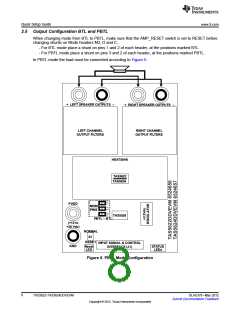
In PBTL mode the load must be connected according to Figure 5:
+ LEFT SPEAKER OUTPUTS –
+ RIGHT SPEAKER OUTPUTS –
LEFT CHANNEL
OUTPUT FILTERS
RIGHT CHANNEL
OUTPUT FILTERS
HEATSINK
TAS5622
TAS5624
PVDD
MODE
PINS
TAS5538
PBTL – BTL
(+12 to
+36 Vdc)
NORMAL
S1
RESET
INPUT SIGNAL & CONTROL
INTERFACE (J1)
GND
Reset
LED
STATUS
LEDs
Figure 5. PBTL Mode Configuration
8
TAS5622-TAS5624DDVEVM
SLAU376–May 2012
Submit Documentation Feedback
Copyright © 2012, Texas Instruments Incorporated

 TI [ TEXAS INSTRUMENTS ]