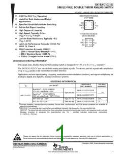
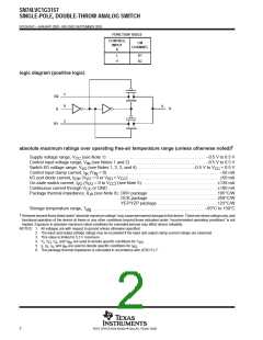
SN74LVC1G3157
SINGLE-POLE, DOUBLE-THROW ANALOG SWITCH
SCES424C – JANUARY 2003 - REVISED SEPTEMBER 2003
analog switch characteristics, T = 25°C
A
FROM
TO
(OUTPUT)
PARAMETER
(INPUT)
TEST CONDITIONS
V
TYP
300
UNIT
CC
1.65 V
2.3 V
3 V
R
= 50 Ω,
= sine wave
(see Figure 6)
L
300
300
300
–54
–54
–54
–54
–57
–57
–57
–57
3
Frequency response
A or Bn
Bn or A
MHz
f
in
†
(switch on)
4.5 V
1.65 V
2.3 V
3 V
R
= 50 Ω,
= 10 MHz (sine wave)
(see Figure 7)
L
Crosstalk
(between switches)
B1 or B2
B2 or B1
dB
f
in
‡
4.5 V
1.65 V
2.3 V
3 V
C
= 5 pF, R = 50 Ω,
L
L
Feed-through attenuation
A or Bn
Bn or A
dB
pC
%
f
in
= 10 MHz (sine wave)
‡
(switch off)
(see Figure 8)
4.5 V
3.3 V
5 V
C
= 0.1 nF, R = 1 MΩ,
L
(see Figure 9)
L
§
S
A
Charge injection
7
1.65 V
2.3 V
3 V
0.1
V = 0.5 V p-p, R = 600 Ω,
I
in
L
0.025
0.015
0.01
f
= 600 Hz to 20 kHz
Total harmonic distortion
A or Bn
Bn or A
(sine wave)
(see Figure 10)
4.5 V
†
‡
§
Adjust f voltage to obtain 0 dBm at output. Increase f frequency until dB meter reads –3 dB.
in
in
Adjust f voltage to obtain 0 dBm at input.
in
Specified by design
switching characteristics over recommended operating free-air temperature range (unless
otherwise noted) (see Figures 5 and 11)
V
= 1.8 V
V
= 2.5 V
V
= 3.3 V
V
= 5 V
CC
0.15 V
CC
0.2 V
CC
0.3 V
CC
0.5 V
FROM
(INPUT)
TO
(OUTPUT)
PARAMETER
UNIT
MIN MAX
MIN MAX
MIN MAX
MIN
MAX
¶
#
t
t
t
A or Bn
S
Bn or A
Bn
2
24
13
1.2
14
0.8
7.6
5.3
0.3
5.7
3.8
ns
ns
ns
pd
en
7
3
3.5
2
2.5
1.5
1.7
0.8
||
7.5
dis
t
0.5
0.5
0.5
0.5
B-M
¶
t
is the slower of t
or t
PLH
. The propagation delay is calculated RC time constant of the typical on-state resistance of the switch and the
PHL
pd
specified load capacitance when driven by an ideal voltage source (zero output impedance).
#
||
t
t
is the slower of t
PZL
is the slower of t
or t
.
en
dis
PZH
or t .
PHZ
PLZ
Specified by design
5
POST OFFICE BOX 655303 • DALLAS, TEXAS 75265

 TI [ TEXAS INSTRUMENTS ]