SN74LVC1T45-Q1
www.ti.com .......................................................................................................................................... SCES677A –SEPTEMBER 2006–REVISED AUGUST 2009
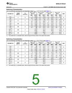
Switching Characteristics
over recommended operating free-air temperature range, VCCA = 1.8 V ± 0.15 V (see Figure 1)
VCCB = 1.8 V
±0.15 V
VCCB = 2.5 V
±0.2 V
VCCB = 3.3 V
±0.3 V
VCCB = 5 V
±0.5 V
FROM
(INPUT)
TO
(OUTPUT)
PARAMETER
UNIT
MIN
3
MAX
MIN
2.2
2.2
2.3
2.1
4.8
2.1
4.9
2.2
MAX
MIN
1.7
1.8
2.1
2
MAX
MIN
1.4
1.7
1.9
1.8
5.1
3.1
2.3
2.0
MAX
tPLH
tPHL
tPLH
tPHL
tPHZ
tPLZ
tPHZ
tPLZ
20.7
17.3
20.7
17.3
22.7
13.5
27.9
19
13.3
11.5
19
11.3
10.1
18.5
15.6
21.4
13.7
13.3
11.4
29.9
28.9
25
10.2
10
A
B
A
A
B
A
B
ns
ns
ns
ns
ns
ns
2.8
3
18.1
15.2
20.1
13.9
11.2
9.4
B
2.8
5.2
2.3
7.4
4.2
15.9
21.5
13.5
14.5
12.2
31.2
30.4
26.8
33
4.7
2.4
3.6
2.3
DIR
DIR
DIR
DIR
(1)
tPZH
39.7
45.2
34.2
40.7
27.5
26.4
24.1
30.1
(1)
tPZL
(1)
tPZH
(1)
tPZL
31.5
(1) The enable time is a calculated value, derived using the formula shown in the enable times section.
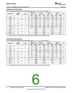
Switching Characteristics
over recommended operating free-air temperature range, VCCA = 2.5 V ± 0.2 V (see Figure 1)
VCCB = 1.8 V
±0.15 V
VCCB = 2.5 V
±0.2 V
VCCB = 3.3 V
±0.3 V
VCCB = 5 V
±0.5 V
FROM
(INPUT)
TO
(OUTPUT)
PARAMETER
UNIT
MIN
2.3
2.1
2.2
2.2
3
MAX
MIN
1.5
1.4
1.5
1.4
2.1
1.3
4.1
2.2
MAX
MIN
MAX
9.4
MIN
1.1
0.9
1
MAX
tPLH
tPHL
tPLH
tPHL
tPHZ
tPLZ
tPHZ
tPLZ
19
15.9
13.3
11.5
11.1
8.9
11.5
10.5
11.5
10.7
11.1
8.9
1.3
1.3
1.4
1.3
2.3
1.3
3.0
2.5
8.1
7.6
A
B
A
A
B
A
B
ns
ns
ns
ns
ns
ns
8.4
11
10.5
9.2
B
10
0.9
3.2
1
11.1
8.9
11.1
8.8
DIR
DIR
DIR
DIR
1.3
6.5
3.5
26.7
21.9
35.2
38.2
27.9
27
14.4
12.6
24.1
24.9
20.4
21.6
13.2
11.4
22.4
23.2
18.3
19.5
1.9
1.6
10.1
8.3
(1)
tPZH
18.8
19.3
16.9
18.7
(1)
tPZL
(1)
tPZH
(1)
tPZL
(1) The enable time is a calculated value, derived using the formula shown in the enable times section.
Copyright © 2006–2009, Texas Instruments Incorporated
Submit Documentation Feedback
5
Product Folder Link(s): SN74LVC1T45-Q1

 TI [ TEXAS INSTRUMENTS ]