PCM9211
SBAS495 –JUNE 2010
www.ti.com
PCM9211 MODULE DESCRIPTIONS
Power Supply
The PCM9211 has four power-supply pins and four ground pins. All ground pins (AGND, AGNDAD, DGND, and
GNDRX) must be connected as closely as possible to the PCM9211. The PCM9211 DVDD and DGND pins are
power-supply pins that support all the onboard digital circuitry for the PCM9211. DVDD should be connected to a
3.3-V supply. DVDD drives the internal power-on reset circuit, making it a startup requirement.
VCC and AGND are analog power-supply power pins that support the DIR analog supply rails.
VDDAD and AGNDAD are dedicated power-supply pins for the onboard ADC. VDDAD should be connected to a
5.0-V power rail.
VDDRX is a dedicated power supply for the coaxial input amplifiers on pins RXIN0 and RXIN1. It should be
connected to a 3.3-V pin. The relative GND pin for this supply is GNDRX. If the coaxial amplifiers are not used
(for example, the application only uses optical inputs), then no power supply is required for the VDDRX.
If the onboard ADC is not used (such as when the application uses an external ADC) then no power supply is
required for the VCCAD pin. This option means that a 5-V rail is not required when the internal ADC is not used.
In such situations, VCCAD should be connected to AGND OR AGNDAD.
Because VCC (3.3 V) is an analog supply (used as part of the power supply for the DIR PLL), care should be
taken to ensure minimum noise and ripple are present. 0.1-mF ceramic capacitors and 10-mF electrolytic
capacitors should be used to decouple each supply pin to the respective relative GND (for example, to decouple
VCCAD and AGNDAD).
Power-Down Function
The PCM9211 has a power-down function that is controlled by the external RST pin or a power control register.
When the RST pin is held at GND, the PCM9211 powers down.
When the device is powered down (that is, RST = GND), all register values are cleared and reset to the
respective default values. By default, all modules are powered on except for the coaxial amplifier.
The other option for powering down the device is to use the Power Control Register (Register 40h). The Power
Control Register allows selective power down of the DIR, ADC, DIT, Coax Amp, and Oscillator circuit without
resetting other registers to the respective default modes.
The advantage of using the registers to power down individual modules of the PCM9211 is that the registers
retain the respective settings rather than resetting to default.
System Reset
The PCM9211 has two sources for reset: the internal power-on reset circuit (hereafter called POR) and the
external reset circuit. See Figure 14 for an illustration of the timing sequence during an internal power-on reset
event. Initialization (reset) is done automatically when VDD exceeds 2.2 V (typ).
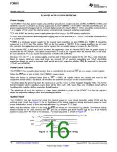
When only the onboard POR is to be used, the RST pin should be connected to VDD directly. An external pull-up
resistor should not be used, because the RST pin has an internal pull-down resistor (typ 50 kΩ). If an external
resistor is used, then the reset is not released. The reset sequence is shown in Figure 11.
VDD = 3.3 V typ
0 V
VDD
MODE
RST
VDD = 2.2 V typ
Tied to VDD or DGND
tRSTL
Figure 11. Required System Reset Timing
16
Submit Documentation Feedback
Copyright © 2010, Texas Instruments Incorporated
Product Folder Link(s): PCM9211

 TI [ TEXAS INSTRUMENTS ]