PCM9211
www.ti.com
SBAS495 –JUNE 2010
OVERVIEW
Introduction
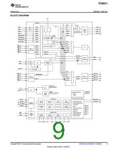
The PCM9211 is an analog and digital front-end device for any media player/recorder. It integrates a 216-kHz
Digital Audio Transceiver (DIX), a 96-kHz stereo ADC, and multiple PCM (I2S, Left-Justified, Right-Justified)
interfaces. Additionally, the device integrates a router that allows any source (ADC, DIR, or PCM) to be routed to
one of three outputs (2x PCM and DIT), thus significantly reducing the number of external components required
to route sources to the core DSP.
Each audio interface of the PCM9211 (that is, the ADC, DIT, and DIR) can operate asynchronously at different
sampling rates, allowing an analog source to be sampled at 96 kHz and to be switched over to an S/PDIF source
driving encoded data at 48 kHz.
The PCM9211 also features a power down function that can be set via hardware pins and registers, ensuring
that the system minimizes power consumption during standby.
Digital Audio Interface Receiver (DIR)
Up to 12 single-ended S/PDIF input pins are available on the PCM9211 DIR module. Two of the 12 S/PDIF
inputs integrate coaxial amplifiers; the other inputs are designed to be directly connected to CMOS sources (up
to +5 V), or standard S/PDIF optical modules.
The DIR module outputs the first 48 bits of channel status data from each frame into specific registers that can
be read via the control interface. In addition, the DIR can detect non-PCM data (such as compressed
multi-channel data) by looking at channel status bits, burst preambles and DTS-CD/LD. When the DIR detects
non-PCM audio data, its status can be configured to the NPCM pin (pin 2). Control of pin 2 (NPCM or INT1) is
set by register 2Bh.
When the DIR encounters an error (for example, when it loses a lock), an error signal can be configured and
sent to the ERROR pin (pin 1). Control of pin 1 (ERROR or Int0) is set by Register 20h. Preamble data PC and
PD (typically used to transmit format information such as Digital Theater Sound, or DTS, or AC-3™ data) can be
read from registers Register 3Ah through Register 3Dh. For more information, see the audio data standard
IEC61937.
The PCM9211 has two interrupt pins (INT0 and INT1) that are shared with other functions (NPCM and ERROR).
The interrupt pins, when configured, can be used for operations such as interrupt transmissions to the DSP (for
example, instructing the DSP where the start of the frame is, etc.). Eight different factors can drive the interrupt.
For more details, see Register 2Ch and Register 2Dh. The interrupt source can also be stored in a register to be
read by a DSP, if required.
When switching from one source to the DIR and vice-versa, additional circuitry in the DIR helps continuity
between the crystal clock source and an internal phase-locked loop (PLL). During a clock source switch, a clock
transition signal can be output that can then be used by the processor to respond accordingly (such as
temporarily muting the output).
An integrated sample rate calculator in the DIR can read and detect both the incoming data rate of the S/PDIF
input as well as the sample rate information bits that are within the channel status data.
The PCM9211 has an internal clock divider that changes its system clock (SCK) output rate in order to maintain
synchronization between the incoming clock and the receiver (based on the autodetector of the incoming data
rate). For example, if the user switches from a 96-kHz source to a 48-kHz source, the divider automatically
detects the switch and changes the clock dividing ratio to ensure that the subsequent DSP continues to receive
the same system clock.
The PCM9211 also has two output ports for the DIR output. The primary output is available from the Main Port
and/or MPIO_B; the secondary port is available through MPIO_A. The dividing ratio of BCK and LRCK for the
primary output is defined by the DIR. The dividing ratio for the second output (normally taken from MPIO_A) is
defined by Register 32h and Register 33h.
When the PLL is locked, the secondary clock source automatically selects the PLL clock (256fS). Otherwise, the
XTI clock source is selected. Register 32h should be used for dividing in the lock status (that is, the PLL source).
When unlocked, Register 33h should be used (the XTI source).
Copyright © 2010, Texas Instruments Incorporated
Submit Documentation Feedback
13
Product Folder Link(s): PCM9211

 TI [ TEXAS INSTRUMENTS ]