ꢀꢁ ꢂꢃ ꢄ ꢅ ꢆ ꢇ ꢀ ꢁꢂ ꢃ ꢄꢅ ꢈ
ꢀꢁꢂ ꢃ ꢄ ꢅ ꢉ ꢇ ꢀ ꢁꢂ ꢃ ꢄꢅ ꢄ
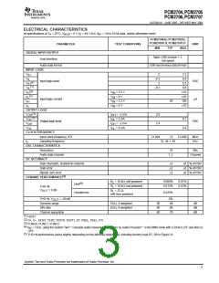
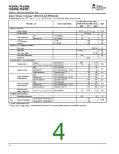
www.ti.com
SLES081A − JUNE 2003 – REVISED MAY 2004
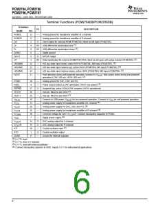
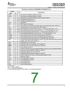
Terminal Functions (PCM2706PJT/PCM2707PJT)
TERMINAL
NAME
I/O
DESCRIPTION
Analog ground for headphone amplifier of L-channel
NO.
26
31
14
23
22
20
17
15
9
AGNDL
—
AGNDR
CK
—
Analog ground for headphone amplifier of R-channel
O
Clock output for external ROM (PCM2706). Must be left open (PCM2707).
(1)
D+
I/O USB differential input/output plus
(1)
I/O USB differential input/output minus
D–
DGND
DOUT
DT
—
O
Digital ground
S/PDIF output / I S data output
2
(1)
I/O Data input/output for external ROM (PCM2706). Must be left open with pullup resistor (PCM2707).
(1)
2
Function select (LOW: I S DATA output, HIGH: S/PDIF output)
FSEL
I
2 (3)
I/O HID key state input (next track), active HIGH (FSEL = 1). I S LR clock output (FSEL = 0).
FUNC0
FUNC1
FUNC2
FUNC3
HID0/MS
HID1/MC
HID2/MD
HOST
5
2
(3)
19
18
4
I/O HID key state input (previous track), active HIGH (FSEL = 1). I S bit clock output(FSEL = 0).
(3)
2
I/O HID key state input (stop), active HIGH (FSEL = 1). I S system clock output (FSEL = 0).
2
(3)
I
I
I
I
I
HID key state input (play/pause), active HIGH (FSEL = 1). I S data input (FSEL = 0).
(3)
6
HID key state input (mute), active HIGH (PCM2706). MS input (PCM2707)
HID key state input (volume up), active HIGH (PCM2706). MC input (PCM2707)
(3)
(3)
7
8
HID key state input (volume down), active HIGH (PCM2706)/MD input (PCM2707)
3
Host detection during self-powered operation. (connect to V
). Max power select during bus-powered
BUS
(2)
operation. (LOW: 100 mA, HIGH: 500 mA).
PGND
PSEL
1
—
I
Analog ground for DAC, OSC and PLL
(1)
16
11
10
24
27
2
Power source select. (LOW: self-power, HIGH: bus-power)
SSPND
TEST
O
I
Suspend flag, active LOW (LOW: suspend, HIGH: operational)
(1)
Test pin. Must be set HIGH
V
V
V
V
V
V
V
V
—
—
—
—
—
—
O
O
I
Connect to USB power (V ) for bus-powered operation. Connect to V for self-powered operation.
BUS DD
BUS
CCL
CCP
CCR
COM
DD
(4)
Analog power supply for headphone amplifier of L-channel
(4)
Analog power supply for DAC, OSC and PLL
Analog power supply for headphone amplifier of R-channel
Common voltage for DAC (V
(4)
30
32
21
28
29
12
13
25
/2). Connect decoupling capacitor to PGND.
CCP
(4)
Digital power supply
L
DAC analog output for L-channel
DAC analog output for R-channel
OUT
OUT
R
(1)
Crystal oscillator input
XTI
XTO
O
—
Crystal oscillator output
ZGND
(1)
Ground for internal regulator
LV-TTL level
(2)
(3)
(4)
LV-TTL level, 5-V tolerant
LV-TTL level with internal pulldown
Connect decoupling capacitor to GND. Supply 3.3 V for self-powered applications.
7

 TI [ TEXAS INSTRUMENTS ]