ꢀꢁ ꢂꢃ ꢄ ꢅ ꢆ ꢇ ꢀ ꢁꢂ ꢃ ꢄꢅ ꢈ
ꢀꢁꢂ ꢃ ꢄ ꢅ ꢉ ꢇ ꢀ ꢁꢂ ꢃ ꢄꢅ ꢄ
www.ti.com
SLES081A − JUNE 2003 – REVISED MAY 2004
DAC
The PCM2704/5/6/7 has a DAC that uses an oversampling technique with 128-f second-order multibit noise
S
shaping. This technique provides extremely low quantization noise in the audio band, and the built-in analog low-pass
filter removes the high-frequency components of the noise-shaping signal. DAC outputs are provided through the
headphone amplifier V
L and V
R can provide 12 mW at 32 Ω as well as 1.8 Vp-p into a 10-kΩ load.
OUT
OUT
DIGITAL AUDIO INTERFACE – S/PDIF OUTPUT
The PCM2704/5/6/7 employs S/PDIF output. Isochronous-out data from the host is encoded to S/PDIF output DOUT
as well as to DAC analog outputs V
Monaural data is converted to the stereo format at the same data rate. S/PDIF output is not supported in the I S I/F
enable mode.
L and V
R. Interface format and timing follows the IEC-60958 standard.
OUT
OUT
2
Channel Status Information
The channel status information is fixed as consumer application, PCM mode, copyright, digital/digital converter. All
other bits are fixed as 0s except for the sample frequency, which is set automatically according to the data received
through the USB.
Copyright Management
Digital audio data output is always encoded as original with SCMS control. Only one generation of digital duplication
is allowed. The implementation of this feature is optional. Note that it is your responsibility for determining whether
to implement this feature in your product or not.
2
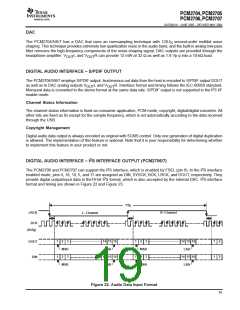
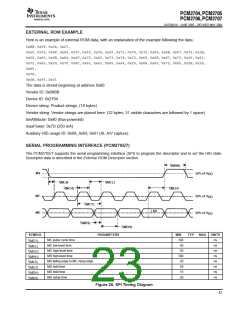
DIGITAL AUDIO INTERFACE – I S INTERFACE OUTPUT (PCM2706/7)
2
2
The PCM2706 and PCM2707 can support the I S interface, which is enabled by FSEL (pin 9). In the I S interface
enabled mode, pins 4, 18, 19, 5, and 17 are assigned as DIN, SYSCK, BCK, LRCK, and DOUT, respectively. They
2
2
provide digital output/input data in the16-bit I S format, which is also accepted by the internal DAC. I S interface
format and timing are shown in Figure 22 and Figure 23.
1/f
S
LRCK
BCK
R−Channel
L−Channel
(64 f )
S
1
1
2
3
14 15 16
LSB
1
1
2
3
14 15 16
LSB
1
1
2
2
DOUT
DIN
MSB
MSB
2
3
14 15 16
LSB
2
3
14 15 16
LSB
MSB
MSB
Figure 22. Audio Data Input Format
19

 TI [ TEXAS INSTRUMENTS ]