ꢀꢁ ꢂꢃ ꢄ ꢅ ꢆ ꢇ ꢀ ꢁꢂ ꢃ ꢄꢅ ꢈ
ꢀꢁꢂ ꢃ ꢄ ꢅ ꢉ ꢇ ꢀ ꢁꢂ ꢃ ꢄꢅ ꢄ
www.ti.com
SLES081A − JUNE 2003 – REVISED MAY 2004
Device Configuration
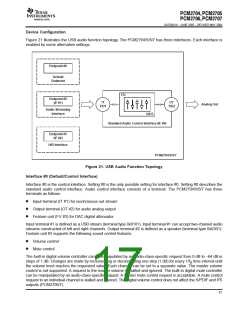
Figure 21 illustrates the USB audio function topology. The PCM2704/5/6/7 has three interfaces. Each interface is
enabled by some alternative settings.
Endpoint #0
Default
Endpoint
FU
Endpoint #2
IT
TID1
OT
TID2
(IF #1)
Analog Out
Audio Streaming
Interface
UID3
Standard Audio Control Interface (IF #0)
Endpoint #5
(IF #2)
HID Interface
PCM2704/5/6/7
Figure 21. USB Audio Function Topology
Interface #0 (Default/Control Interface)
Interface #0 is the control interface. Setting #0 is the only possible setting for interface #0. Setting #0 describes the
standard audio control interface. Audio control interface consists of a terminal. The PCM2704/5/6/7 has three
terminals as follows.
D
D
D
Input terminal (IT #1) for isochronous-out stream
Output terminal (OT #2) for audio analog output
Feature unit (FU #3) for DAC digital attenuator
Input terminal #1 is defined as a USB stream (terminal type 0x0101). Input terminal #1 can accept two-channel audio
streams constructed of left and right channels. Output terminal #2 is defined as a speaker (terminal type 0x0301).
Feature unit #3 supports the following sound control features.
D
D
Volume control
Mute control
The built-in digital volume controller can be manipulated by an audio-class-specific request from 0 dB to –64 dB in
steps of 1 dB. Changes are made by incrementing or decrementing one step (1 dB) for every 1/f time interval until
S
the volume level reaches the requested value. Each channel can be set to a separate value. The master volume
control is not supported. A request to the master volume is stalled and ignored. The built-in digital mute controller
can be manipulated by an audio-class-specific request. A master mute control request is acceptable. A mute control
2
request to an individual channel is stalled and ignored. The digital volume control does not affect the S/PDIF and I S
outputs (PCM2706/7).
17

 TI [ TEXAS INSTRUMENTS ]